
User's Manual


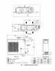


MINIMUM CLEARANCE FOR SERVICE
I_T A]R
!
I
I
I
I
I
I
I_] DU_(NOTE3)
NOTES:
1, Dimensionsare ininches.Dimensions in[ ]are inmillimeters,
2. _ Diroctionofairflow.
3. _erant, d_in, Bnd power conneofionsrubybe _de rear,leftsideor
rightside.
4. Refrigerantismetered by capilla_tubesinthe outdoorunit.Insulatebeth
refrigerantlines.
5. Clearancesof3½ on topofand tothe leftofthefancoilunitareabsolute
minLmu_. Clea_nc_=sof 10" arerecommended.
6. Do not inset{a trapincondensate drainline,Drainisinternallytrapped,
012 )NIT OUTLI_ 012 MOLWWTI_BR:T 7
6 30 24 O0 _ O_
_ 2_ _4] DIA(NOTE 3)
UNIT WEIGHT A B C
4OGNI Lb I Kgl i.. I mml in. I mmlie. I mm
00,118,I°8133401=0011102]28016201160012 24.2 11.0 36.61 930 11.81 300 7.28 185
Fig. 4 -- 40QN Dimensional Drawing
8