
Specifications
SERVICE – Multi Split
WARNING:
Before performing recommended maintenance, be sure unit main power switch is turned off, and be sure all
disconnects for indoor fan coil units are open. These systems typically have one disconnect per fan coil unit. Failure to turn
off unit main power and open all disconnects may result in electrical shock or injury from rotating fan blade.
OUTDOOR FAN
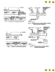
A reinforced wire mount holds the outdoor fan assembly in position. See Fig. 13 for proper mounting positions.
SCROLL COMPRESSORS
The Multi Split condensing units use scroll compressors. The 024 unit has one compressor, and the 048 unit has 2
compressors which are stacked vertically (using a sheet metal stand to support the top compressor). In the event of a
compressor failure, remove and replace the compressor(s) as follows:
1. Attach refrigerant hose to vapor return line service valve of the circuit related to the defective compressor.
2. Recover refrigerant using accepted techniques.
3. Remove discharge and suction piping from compressor by un-sweating. Pass either nitrogen or another inert gas through
the compressor.
4. Remove compressor-mounting bolts. Use a swivel socket to remove the bolt in the rear.
5. Carefully pull compressor stand and piping away from the compressor to remove the compressor.
6. Reverse Steps 1-5 to install the new compressor.
Time-Delay Device Override
The time delay device can be overridden for easier unit servicing by temporarily shorting the time delay device override
connector (P9) located in the control box. The short MUST be removed before the time delay device timer can be cleared.
System Status LED’s and Fault Codes
In normal operating mode, the green LED located on the outdoor unit microprocessor board will flash on and off at a rate of
once per second. Whenever a fan coils unit, compressor, or outdoor fan is energized, a red LED designated for each fan
coil unit will be illuminated. If there is an error condition, a code will be displayed using the green and red system status
LED’s. The green LED will blink its code first, followed by the red LED. The LED’s will flash at a rate of once every 2
seconds, with a 2-second pause between the last red LED flash and the first green LED flash of the next code. See Trouble
Shooting & Fault Code Section #27
HIGH-PRESSURE RELIEF VALVE
Valve is located in compressor. Relief valve opens at a pressure differential of approximately 450 +/- 50 psig between
suction (low side) and discharge (high side) to allow pressure equalization.
INTERNAL CURRENT AND TEMPERATURE SENSITIVE OVERLOAD
Control resets automatically when internal compressor motor temperature drops to a safe level (overloads may require up to
45 minutes to reset). When an internal overload is suspected of being open, check by using an ohmmeter or continuity
tester.
HIGH-PRESSURE SWITCH
This switch, located on discharge line, protects against high discharge pressures caused by such events as overcharge,
condenser-fan motor failure, system restriction, etc. It opens on pressure rise at about 426 psig. If system pressures go
above this setting during abnormal conditions, the switch opens.
WARNING:
DO NOT attempt to simulate these system abnormalities - high pressures pose a serious safety hazard.
High-pressure switch is checked with an ohmmeter. If system pressure is below approximately 320 psig, switch shows
continuity. The high-pressure switch will reset automatically after CLO (compressor lockout switch) has been reset and
time-delay device has completed its timing cycle.
NOTE: If pressure switch needs to be replaced, there is a Schrader valve located under the switch so that system will not
need to be evacuated.
MORE INFO ON NEXT PAGE. CLICK HERE TO CONTINUE READING.