
Specifications


APPLICATION DATA
1. Unit selection
Select equipment to either match or be slightly less than anticipated peak cooling load. This provides better
humidity control, fewer unit cycles, and less part-load operation. Heating and cooling design loads must both be
checked. To meet heating requirements, calculate booster heater in addition to heat pump capacity. Since indoor
unit is off during defrost cycles, it is not necessary for booster heater to meet
total heating requirement. For units used in spaces with high sensible loads, base equipment selection on unit
sensible load, not on total anticipated load. Adjust for anticipated room wet bulb temperature to avoid undersizing
equipment. Heating load using outdoor air must be checked in addition to cooling load. Heating load of outdoor air
can greatly reduce heating capability. When selecting equipment that has outdoor air introduced into the unit,
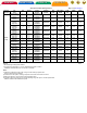
determine the mix conditions of room air and outdoor air at design conditions. The cooling capacity tables in this
literature are based on 80 F edb. Adjust for actual dry-bulb and wet-bulb conditions with the required outdoor air to
select the proper equipment.
2. Unit combinations and coil mixed matches
The 38AN/BK, 38HDC, 38HDL, 38HDS, and 38QR units are the only units approved for use with the 40QA,
40QK AND 40QN duct-free split systems. The 38HDC, HDL, HDS, and QR units may also be used with other fan
coil units in approved combinations.
NOTE:
The 40QAE and 40QKE series heat pump fan coils may also be used with 38HDC, HDL, and HDS
condensing unit to provide systems with cooling and electric heat. Refer to cooling system product literature for
more details.
3. Unit mounting (outdoor)
Unit leveling
— For reliable operation, units should be level in all planes.
Clearance —
Adequate clearance must be provided for airflow. See dimensional drawings for proper clearances.
The heat pump units are designed for free blow application. Air inlets and outlets should not be restricted. Outdoor
fan external static pressure available is less than 0.1 in. wg.
Unit location —
Cooling only units can be stacked 2 high. Heat pump units should not be stacked. Defrosted
condensate from upper unit will re-freeze on lower unit. Units may be wall mounted, pad mounted at ground level,
roof mounted, or mounted on a deck or patio. Be sure water drainage from roof will not drain directly onto the unit.
Units must be mounted so that snow will not obstruct airflow and so that defrosting coil ice may drain freely from
the outdoor unit drain pan. Snow and ice stands must be field fabricated and installed to meet these conditions if
necessary. Contact your local representative for more details. If heat pump units are being installed near a wall, the
condenser air should discharge toward the wall. This will provide inherent coil protection and the best possible
sound and airflow performance. The 38AN units should be mounted with the fan discharge pointed away from the
wall.
4. Unit mounting (indoor)
Unit leveling — For reliable operation, units should be level in all planes. The ceiling-suspended fan coils may
have a slight pitch, but only toward the drain connection.
Clearance
— Provide adequate clearance for airflow. The unit return and discharge should not be obstructed by
furniture, curtains, or anything which may cause unit short cycling or air recirculation. See base unit dimensional
drawings Section #17 for required clearances.
Unit location — When selecting unit location, select a location which will provide the best air circulation for the
room.