R QUALIT TE L 38GL3M21G • 38GL2M18G SURANC E AS 38GL2M12G Y YD'S REGI S LO 38GL_M…G IS O 900 1 38GL4M24G 38GL2M24G R-410A INSTALLATION MANUAL
For operation and maintenance instructions of this unit as well as installation instructions of the indoor unit, refer to the relevant manuals. Contents Page Dimensions and weight ................................................................................................................. Minimum clearances ...................................................................................................................... Connections .................................................................
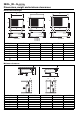
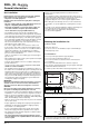
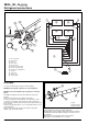
8GL_M…G R-410A Dimensions, weight and minimum clearances Dimensions and weight A A A B B B E D E E D F C E Ø 8,5 F C F C 38GL2M18G 38GL2M24G 38GL3M21G 38GL2M12G kg D Ø 8,5 Ø 8,5 Model A B C D E F E E 38GL4M24G 38GL2M12G 38GL2M18G 38GL2M24G 38GL3M21G 38GL4M24G mm 660 800 800 800 800 mm 504 590 590 590 803 mm 220 300 300 300 300 mm 390 508 508 508 508 mm 135 146 146 146 146 mm 250 330 330 330 330 39 55 64 58 69 kg Minimum clearance
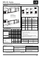
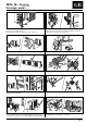
38GL_M…G R-410A Connections and operating limits ENGLISH Connections 햳 A / A1 햶 B2 햵 B / B1 햴 A2 L1 L3 L4 L2 H H H H A1 햲 햲 햳 햴 햵 햶 L3 햲 L2 H L4 H H H 햶 B2 L1 A A2 B1 A2 B B B2 38GL4M24G 38GL3M21G Pipe diameter Liquid Gas (Liquid) (Suction) mm (inches) mm (inches) Indoor unit 2M12G A1 A2 6.35 (1/4") 6.35 (1/4") 9.52 (3/8") 12.70 (1/2") (note 1) 2M18G A B 6.35 (1/4") 6.35 (1/4") 9.52 (3/8") 9.52 (3/8") 2M24G A B 6.35 (1/4") 6.35 (1/4") 12.70 (1/2") 12.
38GL_M…G R-410A General information Unit installation • Dispose of the packaging material in accordance with local requirements. R-410A systems operate at higher pressures than standard R-22 systems. Do not use R-22 service equipment or components on R-410A equipment. • This equipment contains refrigerant that must be disposed of in a proper manner. When disposing of the unit after its operational life, remove it carefully.
38GL_M…G R-410A Warnings: avoid.... ENGLISH Disconnecting the refrigerant connections after installation: thiis will cause refrigerant leaks. Connecting the condensate drain pipe to the outdoor unit. Excessive height difference between indoor and outdoor unit (see Table II "Connections"). Excessive distance between indoor and outdoor units. (see Table II "Connections"). Predominant head winds. Unnecessary turns and bends in the connecting pipes.
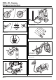
38GL_M…G R-410A Refrigerant connections No moisture. No dust. Charge liquid-no gas. No leak. No mineral oil. Copper tubes during storage. Neat. 1/2” UNF (R-410A) 7/16” UNF (R-22) Use tools designed for R-410A higher pressure. Keep inside clean. Dry nitrogen brazing. Min. – 100 kPa (– 755 mmHg) Vacuum. GB - 6 2-stage vacuum pump. Replace oil regularly.
38GL_M…G R-410A Refrigerant connections ENGLISH Flaring the ends of the tubing Remove protective caps from copper tube ends. Position tube end downward, cut the tube to the requested length and remove the burrs with a reamer. Do not leave system open to atmosphere any longer than minimum required for installation. Oil in the compressor is extremely susceptible to moisture absorption. Always keep ends of tubing sealed during installation.
38GL_M…G R-410A Refrigerant connections 햸 햶 햹 햸 햷 햻 햸 햹 햻 햵 햺 햳햲 햴 햹 햻 햻 햸 햹 햸 햹 햴 햽 햲 햳 햴 햵 햶 햷 햸 햹 햺 햻 햽 햾 Three-way valve Needle valve Valve cap Valve needle Two-way valve Allen (hex. head) wrench Gas line (large diameter) Liquid line (small diameter) Flare nut Indoor unit Outdoor unit Vacuum pump 햾 Air purging Use only a vacuum pump to purge air from the piping. 헁 NEVER use the system compressor as a vacuum pump. NEVER use the unit refrigerant gas to purge the connecting pipes.
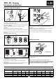
38GL_M…G R-410A Electrical connections ENGLISH Cooling only unit L N R1 C1 Y1 R2 C2 Y2 R3 C3 Y3 R4 C4 Y4 L N R C Y A / A1 R C Y R C Y R C Y A2 B / B1 B2 햲 햳 10 Terminal box legend 10 햲 햳 쐃 쐇 쐋 쐏 100 Mains supply connecting cable (field wiring). Connecting cable, indoor-outdoor units (field wiring). Indoor unit Outdoor unit Main switch Time-delay fuse or circuit breaker (see table IV "Electrical data").
38GL_M…G R-410A Electrical connections • Make electrical connections between units prior to proceeding to mains supply unit connection. • Before proceeding with the unit connection to the mains supply locate live L and neutral N, then make connections as shown in the wiring diagram. • Ensure that mains supply connection is made through a switch that disconnects all poles, with contact gap of a least 3 mm.
38GL_M…G R-410A Testing, Pump Down and check the refrigerant charge 15 ENGLISH 24 22 20 쐃 10 18 쐋 16 14 5 12 20 25 30 35 40 쐇 쐃 Superheat °C 쐇 Condenser entering dry bulb temperature °C 쐋 Evaporator entering wet bulb temperature °C Testing IMPORTANT: Test each single unit separately. Pump Down Pump down is an operation intended to collect all the system refrigerant in the outdoor unit.
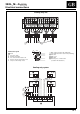
38GL_M…G R-410A Check the refrigerant charge Refrigerant charge control 38GL2M18G - 38GL2M24G 38GL2M12G 햾 헂 햽 햲 Ta Te 헁 햲 Ta Te 햻 Ta 햷 햵 햳 햴 햺 햵 햹 햶 햷 햳 햶 햸 38GL3M21G 헂 햾 햲 Outdoor unit 햽 Ta 햲 Te 햻 햳 Circuit A compressor 햴 Circuit B compressor 햵 Outdoor unit coil 햶 Filter 햷 Expansion device (Capillary) 햸 Expansion device (Accurater) 햹 Distributor 햷 햴 햵 햸 햺 햻 Service valve 햽 Indoor unit coil A1 햾 Indoor unit coil A2 햿 Indoor unit coil B1 햹 햶 햺 Solenoid valve 헀 Indoor u
38GL_M…G R-410A Check the refrigerant charge and unit maintenance ENGLISH Refrigerant charge control 38GL4M24G 햿 햾 햲 Outdoor unit 햳 Circuit A compressor 햴 Circuit B compressor 헀 햽 햵 Outdoor unit coil 햶 Filter 햷 Expansion device (Capillary) 햲 Ta 햻 Te 햸 Expansion device (Accurater) 햹 Distributor 햺 Solenoid valve 햻 Service valve 햽 Indoor unit coil A1 햷 햴 햺 햾 Indoor unit coil A2 햿 Indoor unit coil B1 헀 Indoor unit coilB2 헁 Indoor unit coil A 헂 Indoor unit coil B 햹 햵 Gas Liquid + Gas 햳 햶 L
38GL_M…G R-410A Troubleshooting, guide for the owner and accessories Troubleshooting Compressor and fan of the outdoor unit will not start: • Unit not energized; check the mains power connections. • Main switch OFF; check and put to the ON position. • Main switch fuses have blown; replace. • Wait for 3 minutes; compressor cycling protection is on. • Accessory pressure switch open; check and eliminate cause. • Mains voltage too low. • Electrical connections loose or wrong; check and repair.
L010124H50 - 0202 Via R. Sanzio, 9 - 20058 Villasanta (MI) Italy - Tel. 039/3636.1 The manufacturer reserves the right to change any product specifications without notice. Order No. 13816-74M10, February 2002. Supersedes Order No. 13816-74M10, April 2001.