
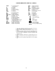
Specifications

To Clean Outdoor Coil (Outdoor Unit)
Some metal parts and sharp fins of outdoor unit coil can
cause personal injury during cleaning. Clean coil
carefully.
To clean the outdoor coil:
1. Remove any dirt or obstruction from discharge opening.
2. Use a garden hose to spray water on the coil. Debris that
collects between coil fins inhibits heat transfer — direct
the water spray between coil fins to flush out debris.
Cleaning Condensate Drains — Clean all drains and
drain pans at the start of each cooling season. Check the flow
by pouring water into the drain.
SERVICE
When servicing unit, turn off all electric power to unit
to avoid shock hazard or injury from rotating parts.
Do not vent refrigerant to atmosphere when servicing
unit. Reclaim refrigerant during system repair or unit
removal.
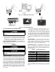
Diagnostic Codes — This unit is equipped with a mi-
croprocessor control which continuously monitors the op-
eration of the unit. If an operational fault is detected, a fault
is indicated by the flashing of the green ‘‘UNIT ON’’ light
on the front of the fan coil unit. A red LED (light-emitting
diode) indicator light, located on the control board in the
control box of the indoor unit, will emit a flash code which
can be used to troubleshoot a system problem. The control
will continue to monitor the unit and, if the conditions which
cause the fault are cleared, the unit will return to normal
operation. If the fault code is present for 5 cycles of the unit,
the unit will be locked out and the alarm is indicated by the
flashing of the green ‘‘UNIT ON’’ light on the front of the
fan coil unit.
To access the LED indicator light, remove the front cover
of the unit by removing the 3 screws holding it in place.
If the LED indicator light continuously flashes on for one
second, then off for one second, the control is functioning
properly and no fault is present. A fast flashing LED indi-
cates that a fault has been detected. Table 7 lists the number
of quick flashes and the associated fault. If the system does
not operate, and the LED indicator does not flash, either the
power to the control board is off, or the control board has
failed.
System Tests — System tests listed below are per-
formed continuously by the microprocessor. If a fault is
indicated, then the system allows only limited operation un-
til the problem is resolved. If the problem resolves itself,
then the code is cleared and operation resumes.
THERMISTOR TESTS — Each thermistor is tested for high
limit out of range (shorted condition) and low limit out of
range (open condition). If the thermistor is out of range, the
fault status indicator comes on and the LED flashes the ap-
propriate fault code.
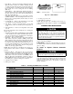
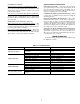
Table 7 — System Fault Codes
NO. OF QUICK
LED FLASHES
SYSTEM FAULT
2 Room Air Thermistor
3 Indoor Coil Thermistor
4 Outdoor Coil Thermistor*
5 Compressor Malfunction
6 Reversing Valve Malfunction*
7 Outdoor Air Thermistor*
8 Indoor Fan Failure
9 Discharge Air Thermistor
LED — Light-Emitting Diode
*Heat pump systems only.
NOTE: If the LED light continuously flashes on for one second, then
off for one second, the control is functioning properly and no fault is
present.
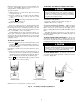
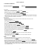
PRESS SET TIME PRESSTA TA
Fig. 22 — Setting The Current Time
REMOVE FILTER VACUUM CLEAN RINSE WITH WATER
Fig. 23 — Air Filter Maintenance
14