40MAQ / 38MAQ High- Wall Ductless Split System Sizes 09 to 30 Product Data INDUSTRY LEADING FEATURES / BENEFITS A PERFECT BALANCE BETWEEN BUDGET LIMITS, ENERGY SAVINGS AND COMFORT. The 38/40MAQ series ductless split systems are a matched combination of an outdoor condensing unit and an indoor fan coil unit connected only by refrigerant tubing and wires. The fan coil is mounted on the wall, near the ceiling.
LOW SOUND LEVELS BUILT- IN RELIABILITY When noise is a concern, the ductless split systems are the answer. The indoor units are whisper quiet. There are no compressors indoors, either in the conditioned space or directly over it, and there is none of the noise usually generated by air being forced through ductwork. When sound ordinances and proximity to neighbors demand quiet operation, the 38MAQ unit is the right choice: The advanced, horizontal airflow design distributes air more evenly over the coil.
MODEL NUMBER NOMENCLATURE INDOOR UNIT 40 MA Q B 09 B - - 3 40= FAN COIL UNIT VOLTAGE 1 =115 - 1 - 60 3 = 208/230 - 1 - 60 MA = MODEL SYSTEM TYPE Q = HEAT PUMP MAXIMUM NUMBER OF FAN COIL UNITS THAT CAN BE CONNECTED TO THE OUTDOOR UNIT B=1:1 NOT USED NOMINAL CAPACITY 09 - 3/4 TON 12 - 1 TON 18 - 1 - 1/2 TONS 24 - 2 TONS 30 - 2 - 1/2 TONS INDOOR FAN COIL TYPE B= HIGH - WALL OUTDOOR UNIT 38 MA Q B 09 - - - 3 38 = OUTDOOR UNIT VOLTAGE 1 =115 - 1 - 60 3 = 208/230 - 1 - 60 MA = MODEL SYSTE
STANDARD FEATURES AND ACCESSORIES Ease Of Installation Mounting Brackets Low Voltage Controls Comfort Features Microprocessor Controls Wired Remote Control Wireless Remote Control Automatic Horizontal Air Sweep Air Direction Control Auto Restart Function Cold Blow Protection On Heat Pumps Freeze Protection Mode On Heat Pumps Turbo Mode Silence Mode Auto Changeover On Heat Pumps Follow Me Energy Saving Features Sleep Mode Stop/Start Timer 46° F Heating Mode (Heating Setback) Safety And Reliability 3 Minute T
DIMENSIONS - INDOOR Fig. 2 – Indoor unit Unit Size W in (mm) D in (mm) H in (mm) 9K/12K 32.9 (835) 7.8 (198) 11.0 (280) Operating Weight lb (kg) 19.2 (8.7) 18K 39.0 (990) 8.6 (218) 12.4 (315) 26.5 (12.0) 24K/30K 46.7 (1186) 10.2 (258) 13.4 (343) 40.8 (18.5) DIMENSIONS - OUTDOOR Fig. 3 – Outdoor unit Operating Weight lb (kg) Model W in (mm) D in (mm) H in (mm) L1 in (mm) L2 in (mm) 9K/12K 32.0 (810) 12.2 (310) 22.0 (558) 20.9 (530) 11.4 (290) 82.5 (37.4) 18K 32.
CLEARANCES - INDOOR CEILING 6" (0.15m) min. 5" (0.13m) min. 5" (0.13m) min. 6' (1.8m) FLOOR Fig. 4 – Indoor Unit Clearance CLEARANCES - OUTDOOR A Air-inlet E D B C Air-outlet Fig. 5 – Clearances Outdoor Minimum Value in.
SPECIFICATIONS - HEAT PUMP UNITS (MAQ SERIES) Size 9 12 9 12 18 24 30 Outdoor Model 38MAQB09---1 38MAQB12---1 38MAQB09---3 38MAQB12---3 38MAQB18---3 38MAQB24---3 38MAQB30---3 Indoor Model 40MAQB09B--1 40MAQB12B--1 40MAQB09B--3 40MAQB12B--3 40MAQB18B--3 40MAQB24B--3 40MAQB30B--3 Energy Star YES YES YES YES YES YES NO Cooling Rated Capacity Btu/h 9,000 12,000 9,000 12,000 17,500 23,000 30,000 Cooling Cap.
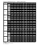
COOLING PERFORMANCE DATA - 38/40MAQ (HEAT PUMP) Model Indoor Conditions DB Cooling Indoor Conditions WB 69.8F(21C) 59F(15C) 75.2F(24C) 62.6F(17C) 80.6F(27C) 66.2F(19C) 89.6F(32C) 73.4F(23C) 69.8F(21C) 59F(15C) 75.2F(24C) 62.6F(17C) 80.6F(27C) 66.2F(19C) 89.6F(32C) 73.4F(23C) 69.8F(21C) 59F(15C) 75.2F(24C) 62.6F(17C) 80.6F(27C) 66.2F(19C) 89.6F(32C) 73.4F(23C) 69.8F(21C) 59F(15C) 75.2F(24C) 62.6F(17C) 80.6F(27C) 66.2F(19C) 89.6F(32C) 73.4F(23C) 69.8F(21C) 59F(15C) 75.
HEATING PERFORMANCE DATA - - 38/40MAQ (HEAT PUMP) Model 38-40MAQ Heating 59F(15C) 64.4F(18C) 09(115V) 69F(20.5C) 71.6F(22C) 59F(15C) 64.4F(18C) 12(115V) 69F(20.5C) 71.6F(22C) 59F(15C) 64.4F(18C) 09 (208-230V) 69F(20.5C) 71.6F(22C) 59F(15C) 64.4F(18C) 12 (208-230V) 69F(20.5C) 71.6F(22C) 59F(15C) 64.4F(18C) 18 (208-230V) Outdoor conditions (DB) Indoor Conditions DB 69F(20.5C) 71.6F(22C) 59F(15C) 64.4F(18C) 24 (208-230V) 69F(20.5C) 71.6F(22C) 59F(15C) 64.4F(18C) 30 (208-230V) 69F(20.
APPLICATION DATA UNIT SELECTION METERING DEVICES Select equipment to either match or be slightly less than anticipated peak load. This provides better humidity control, fewer unit cycles, and less part- load operation. For units used in spaces with high sensible loads, base equipment selection on unit sensible load, not on total anticipated load. Adjust for anticipated room wet bulb temperature to avoid undersizing equipment.
WIRING Recommended Connection Method for Power and Communication Wiring (To minimize communication wiring interference) Power Wiring: The main power is supplied to the outdoor unit. The field supplied connecting cable from the outdoor unit to indoor unit consists of three (3) wires and provides the power for the indoor unit. Two wires are high voltage AC power and one is a ground wire.
AIR FLOW DATA 9K 12K 9K 12K 18K 24K 30K (115V) (115V) (208-230V) (208-230V) (208-230V) (208-230V) (208-230V) Turbo 380 380 380 380 680 870 870 SYSTEM SIZE Indoor (CFM) High 360 360 360 360 650 780 780 Medium 290 300 290 300 450 620 620 Low 210 210 210 210 310 520 520 1200 1200 1200 1200 1390 2130 2130 Outdoor (CFM) AIR THROW DATA Unit Capacity Max Approximate Air Throw ft. (m) Approximate Air Throw ft. (m) range 9K, 12K 23 (7) 11 (3.
FAN AND MOTOR SPECIFICATIONS System size Indoor fan Indoor fan Outdoor fan 9K 12K 18K 24K 30K (208-230V) (208-230V) (208-230V) (208-230V) (208-230V) AS AS AS AS AS AS AS Type GL-98*655-N GL-98*655-N GL-98*655-N GL-98*655-N GL-107.5*760-IN GL-118*895-IN GL-118*895-IN Diameter inch 3.8 3.8 3.8 3.8 4.2 4.6 4.6 Height inch 25.8 25.8 25.8 25.8 30 35.2 35.
BLACK RED BLUE CN1 6(5) PART NAME Output:Pin5&6(12V) Pin1-Pin4:Pulse waveform,(0-12V) Input:Pin1-Pin2(0-1.8V) Input: Pin1,Pin3 ,Pin4,Pin5(0-1.
BLUE BLACK WHITE WHITE CN7 AMBIENT SENSOR INPUT or OUTPUT VALUE Output:Pin5&6(12V) Pin1-Pin4:Pulse waveform,(0-12V) Input:Pin3-4 (3.3V) Pin2(0V),Pin1,Pin5(0-3.3V) Input:Pin1 (3.3V) Pin2(0-3.
RED Y/G BLUE / / Y/G CN6 CN6-1 / / 6 / / YELLOW BLACK CN8 CN7 CN2 CN3 CN4 &1 +($7 CN414 3 TEMPERATURE SENSOR Maximum voltage:DC5V Indoor fan interface,Maximum voltage:DC310V Stepper motor interface,Maximum voltage between the lines:DC12V Ground Room temperature sensor interface,maximum voltage:DC5V Pipe temperature sensor interface,maximum voltage:DC5V Display interface,maximum voltage between the lines:DC5V INPUT or OUTPUT VALUE Input: 230V High voltage Output: Connection of the
%/8( %/8( 9 85 %/$&.
U T3 18 BLACK RED INPUT or OUTPUT VALUE CN52 CN53 CN51 CN54 U V W 7 SV L-PRO T4 H-PRO T3 HEAT2 Output: Pulse(0-380V) for compressor U V W INPUT or OUTPUT VALUE Input: 230V High voltage Output: Connection of the high voltage Output: Pulse(0-320V) for DC FAN Input:Pin1 (5V) Pin2(0-5V) Output: High voltage for 4-way control Output: 230V High voltage for HEATER1 Output: 230V High voltage for HEATER2 Input:Pin3-4 (5V) Pin2(0V),Pin1,Pin5(0-5V) Input:Pin1~3 (0V) Pin2~4(0-5V) Output: Connectio
GUIDE SPECIFICATIONS INDOOR WALL- MOUNTED DUCTLESS UNITS Size Range: 3/4 to 2 1/2 Ton Nominal Cooling and Heating Capacity Carrier Model Number: 40MAQ PART 1 - GENERAL 1.01 System Description Indoor, wall- mounted, direct- expansion fan coils are matched with the heat pump outdoor unit. 1.02 Agency Listings Unit shall be rated per AHRI Standards 210/240 and listed in the AHRI directory as a matched system. 1.
GUIDE SPECIFICATIONS HORIZONTAL DISCHARGE OUTDOOR UNITS Size Range: 3/4 to 2 1/2 Ton Nominal Cooling and Heating Capacity Carrier Model Number:38MAQ PART 1 - GENERAL 1.01 System Description A. Outdoor air- cooled split system compressor sections suitable for on- the- ground, rooftop, wall hung or balcony mounting. Units shall consist of a rotary compressor, an air- cooled coil, propeller- type draw- through outdoor fan, reversing valve (HP), accumulator (HP units), metering device(s), and control box.