
Installation Instructions
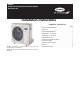
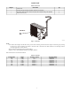
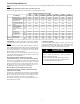
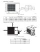
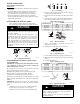
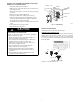
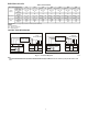
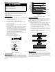
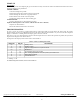
Table Of Contents

4
SYSTEM REQUIREMENTS
Allow sufficient space for airflow and service of the unit. See Fig. 3 for the required minimum distances between the unit, walls or ceilings.
Piping
IMPORTANT: Both refrigerant lines must be insulated separately.
Table 3 contains piping information for the product covered within this document.
Table 3—Piping and Refrigerant Information
SYSTEM SIZE
9K 12K 9K 12K 18K 24K 30K
(115V) (115V) (208-230V) (208-230 V) (208-230 V) (208-230 V) (208-230 V)
Piping
Min. Piping Length ft (m) 10 (3) 10 (3) 10 (3) 10 (3) 10 (3) 10 (3) 10 (3)
Standard Piping Length ft (m) 25 (7.5) 25 (7.5) 25 (7.5) 25 (7.5) 25 (7.5) 25 (7.5) 25 (7.5)
Max. outdoor-indoor
height difference
ft (m) 32 (10) 32 (10) 32(10) 32(10) 65(20) 65(20) 82(25)
Max. Piping Length with
no additional refrigerant
charge
ft (m) 26 (8) 26(8) 26(8) 26(8) 26(8) 26(8) 26(8)
Max. Piping Length ft (m) 82 (25) 82(25) 82(25) 82(25) 98(30) 98(30) 164 (50)
Additional refrigerant
charge (between
Standard – Max piping
length)
Oz/ft
(g/m)
0.16 (15) 0.16 (15) 0.16 (15) 0.16 (15) 0.16 (15) 0.32 (30) 0.32 (30)
Gas Pipe (size -
connection type)
in
(mm)
3/8 (9.52) 1/2 (12.7) 3/8 (9.52) 1/2 (12.7) 1/2 (12.7) 5/8 (16) 5/8 (16)
Liquid Pipe (size -
connection type)
in 1/4 in 1/4 in 1/4 in 1/4 in 1/4 in 3/8 in 3/8 in
(mm) 6.35 6.35 6.35 6.35 6.35 9.52 9.52
Refrigerant
Refrigerant Type R410A R410A R410A R410A R410A R410A R410A
Charge Amount
Lbs
(kg)
2.76
(1.25)
2.76
(1.25)
2.76
(1.25)
2.76
(1.25)
4.19
(1.90)
5.18
(2.35)
6.62
(3.00)
IMPORTANT: All outdoor units have an electronic expansion
valve which manages the refrigerant flow of the fan coil connected.
Wiring
All wires must be sized per NEC (National Electrical Code) or
CEC (Canadian Electrical Code) and local codes. Use the Electrical
Data table MCA (minimum circuit amps) and MOCP (maximum
over current protection) to correctly size the wires and the
disconnect fuse or breakers respectively.
Per the caution note, only stranded copper conductors with a 600
volt rating and double insulated copper wire must be used. The use
of BX cable is not recommended.
Recommended Connection Method for Power and
Communication Wiring − Power and Communication Wiring:
The main power is supplied to the outdoor unit. The field supplied
14/3 power/communication wiring from the outdoor unit to the
indoor unit consists of four (4) wires and provides the power for
the indoor unit. Two wires are high voltage AC power, one is
communication wiring and the other is a ground wire.
Recommended Connection Method for Power and
Communication Wiring (To minimize communication wiring
interference) Power Wiring:
The main power is supplied to the outdoor unit. The field supplied
power wiring from the outdoor unit to the indoor unit consists of
three (3) wires and provides the power for the indoor unit. Two
wires are high voltage AC power and one is a ground wire.
To minimize voltage drop, the factory recommended wire size is
14/2 stranded with a ground.
Communication Wiring:
A separate shielded stranded copper conductor only, with a 600
volt rating and double insulated copper wire, must be used as the
communication wire from the outdoor unit to the indoor unit.
Please use a separate shielded 16GA stranded control wire.
CAUTION
!
EQUIPMENT DAMAGE HAZARD
Failure to follow this caution may result in equipment
damage or improper operation.
S Wires should be sized based on NEC and local codes.
S Use copper conductors only with a minimum 600 volt
rating and double insulated copper wire.