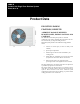
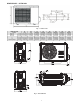
38MA*R Outdoor Unit Single Zone Ductless System Sizes 09 to 36 Product Data INDUSTRY LEADING FEATURES / BENEFITS A PERFECT BALANCE BETWEEN BUDGET LIMITS, ENERGY SAVINGS AND COMFORT. The 38MA*R series ductless split systems are a matched combination of an outdoor condensing unit and an indoor fan coil unit connected only by refrigerant tubing and wires.
LOW SOUND LEVELS BUILT−IN RELIABILITY When noise is a concern, the ductless split systems are the answer. The indoor units are whisper quiet. There are no compressors indoors, either in the conditioned space or directly over it, and there is none of the noise usually generated by air being forced through ductwork. When sound ordinances and proximity to neighbors demand quiet operation, the 38MA*R unit is the right choice. The advanced, horizontal airflow design distributes air more evenly over the coil.
MODEL NUMBER NOMENCLATURE OUTDOOR UNIT 38 MA Q B 09 R -- 3 38 = OUTDOOR UNIT VOLTAGE 1 =115-1-60 3 = 208/230-1-60 MA = MODEL SYSTEM TYPE Q = HEAT PUMP MAXIMUM NUMBER OF FAN COIL UNITS THAT CAN BE CONNECTED TO THE OUTDOOR UNIT B=1:1 NOT USED NOMINAL CAPACITY 09 - 3/4 TON 12 - 1 TON 18 - 1-1/2 TONS 24 - 2 TONS 30 - 2-1/2 TONS 36 - 3 TONS UNIT TYPE R = OUTDOOR UNIT Use of the AHRI Certified TM Mark indicates a manufacturer’s participation in the program For verification of certification for ind
STANDARD FEATURES AND ACCESSORIES Ease Of Installation Low Voltage Controls Energy Saving Features Stop/Start Timer 46°F Heating Mode (Heating Setback) Safety And Reliability 3 Minute Time Delay For Compressor Over Current Protection For Compressor Condenser High Temp Protection in Cooling Mode Ease Of Service And Maintenance Diagnostics Liquid Line Pressure Taps Application Flexibility Crankcase Heater Base pan Heater OUTDOOR UNITS S Crankcase Heater S The crankcase heater is standard on all unit sizes
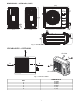
DIMENSIONS − OUTDOOR Fig. 1 – Outdoor Unit 38MAR UNIT SIZE Voltage Height (H) in (mm) Width (W) in (mm) Depth (D) in (mm) L1 in (mm) L2 in (mm) Operating Weight Lbs (kg) 9K 115V 21.81(554) 32.09(815) 13.11(333) 20.24 (514) 13.39 (340) 82.9(37.6) 12K 115V 21.81(554) 32.09(815) 13.11(333) 20.24 (514) 13.39 (340) 82.9(37.6) 9K 208/230V 21.81(554) 32.09(815) 13.11(333) 20.24 (514) 13.39 (340) 91.5(41.5) 12K 208/230V 21.81(554) 32.09(815) 13.11(333) 20.24 (514) 13.39 (340) 91.5(41.5) Fig.
DIMENSIONS − OUTDOOR (CONT) Fig.
DIMENSIONS − OUTDOOR (CONT) Fig. 4 – Sizes 24K, 30K, and 36K CLEARANCES − OUTDOOR A Air-inlet E D B C Air-outlet Fig. 5 – Clearances Outdoor MINIMUM VALUE in.
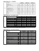
SPECIFICATIONS − OUTDOOR HEAT PUMP System Electrical Operating Range Piping Refrigerant Outdoor Coil Compressor Outdoor SIZE Outdoor Model Voltage, V/Ph/Hz Phase, Cycle MCA A. MOCP A. Fuse Rating Cooling Outdoor DB °F(°C) Min - Max Heating Outdoor DB °F(°C) Min - Max Total Piping ft (m) Length Piping Lift* ft (m) Pipe Connection in (mm) Size Liquid Pipe Connection in (mm) Size Suction Type Metering Device Charge lbs (kg) Face Area Sq. Ft. No.
PERFORMANCE − CASSETTE Indoor Model 40MBQB09C--3 40MBQB12C--3 40MBQB18C--3 619REQ009CBMA 619REQ012CBMA 619REQ018CBMA Energy Star Cassette YES YES YES Cooling Rated Capacity Btu/h 9,000 12,000 16,000 Cooling Cap. Range Min - Max Btu/h 3,500~11,000 4,000~13000 4,500~18,000 SEER 20.0 19.5 20.0 EER 13.0 12.5 12.
COMPATIBILITY TABLE OUTDOOR UNIT INDOOR UNIT HIGH WALL CASSETTE DUCTED FLOOR CONSOLE 38MAQB09R--1 40MAQB09B--1 619PAQ009BBMA 40MAQB12B--1 619PAQ012BBMA 40MAQB09B--3 619PEQ009BBMA 40MAQB12B--3 619PEQ012BBMA 40MAQB18B--3 619PEQ018BBMA 40MAQB24B--3 619PEQ024BBMA 40MAQB30B--3 619PEQ030BBMA 40MAQB36B--3 619PEQ036BBMA 40MBQB09C--3 619REQ009CBMA 40MBQB12C--3 619REQ012CBMA 40MBQB18C--3 619REQ018CBMA 40MBQB09D--3 619REQ009DBMA 40MBQB12D--3 619REQ012DBMA 40MBQB18D--3 619REQ018DBMA 40
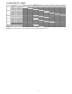
COOLING PERFORMANCE DATA − HIGH WALL MODEL 09 (115V) 12 (115V) 09 (208-230V) 12 (208-230V) 18 (208-230V) 24 (208-230V) 30 (208-230V) 36 (208-230V) COOLING Indoor Conditions DB DB WB 69.8F (21C) 59F (15C) 75.2F (24C) 62.6F (17C) 80.6F (27C) 66.2F (19C) 89.6F (32C) 73.4F (23C) 69.8F (21C) 59F (15C) 75.2F (24C) 62.6F (17C) 80.6F (27C) 66.2F (19C) 89.6F (32C) 73.4F (23C) 69.8F (21C) 59F (15C) 75.2F (24C) 62.6F (17C) 80.6F (27C) 66.2F (19C) 89.6F (32C) 73.4F (23C) 69.
HEATING PERFORMANCE DATA − HIGH WALL MODEL HEATING Indoor Conditions DB 59F (15C) 09 (115V) 64.4F (18C) 69F (20.5C) 71.6F (22C) 59F (15C) 12 (115V) 64.4F (18C) 69F (20.5C) 71.6F (22C) 59F (15C) 09 (208-230V) 64.4F (18C) 69F (20.5C) 71.6F (22C) 59F (15C) 12 (208-230V) 64.4F (18C) 69F (20.5C) 71.6F (22C) 59F (15C) 18 (208-230V) 64.4F (18C) 69F (20.5C) 71.6F (22C) 59F (15C) 24 (208-230V) 64.4F (18C) 69F (20.5C) 71.6F (22C) 59F (15C) 30 (208-230V) 64.4F (18C) 69F (20.5C) 71.
COOLING PERFORMANCE DATA − CASSETTE MODEL DB 09 (208-230V) 12 (208-230V) 18 (208-230V) COOLING Indoor Conditions DB WB 69.8F (21C) 59F (15C) 75.2F (24C) 62.6F (17C) 80.6F (27C) 66.2F (19C) 89.6F (32C) 73.4F (23C) 69.8F (21C) 59F (15C) 75.2F (24C) 62.6F (17C) 80.6F (27C) 66.2F (19C) 89.6F (32C) 73.4F (23C) 69.8F (21C) 59F (15C) 75.2F (24C) 62.6F (17C) 80.6F (27C) 66.2F (19C) 89.6F (32C) 73.
COOLING PERFORMANCE DATA − DUCTED STYLE COOLING Indoor Conditions DB MODEL 09 (208-230V) 12 (208-230V) 18 (208-230V) 24 (208-230V) OUTDOOR CONDITIONS (DB) DB WB 69.8F (21C) 59F (15C) 75.2F (24C) 62.6F (17C) 80.6F (27C) 66.2F (19C) 89.6F (32C) 73.4F (23C) 69.8F (21C) 59F (15C) 75.2F (24C) 62.6F (17C) 80.6F (27C) 66.2F (19C) 89.6F (32C) 73.4F (23C) 69.8F (21C) 59F (15C) 75.2F (24C) 62.6F (17C) 80.6F (27C) 66.2F (19C) 89.6F (32C) 73.4F (23C) 69.8F (21C) 59F (15C) 75.
HEATING PERFORMANCE DATA − DUCTED STYLE MODEL HEATING Indoor Conditions DB 59F (15C) 09 (208-230V) 64.4F (18C) 69F (20.5C) 71.6F (22C) 59F (15C) 12 (208-230V) 64.4F (18C) 69F (20.5C) 71.6F (22C) 59F (15C) 18 (208-230V) 64.4F (18C) 69F (20.5C) 71.6F (22C) 59F (15C) 24 (208-230V) 64.4F (18C) 69F (20.5C) 71.
COOLING PERFORMANCE DATA − FLOOR CONSOLE MODEL 09 (208-230V) 12 (208-230V) COOLING Indoor Conditions DB DB WB 69.8F (21C) 59F (15C) 75.2F (24C) 62.6F (17C) 80.6F (27C) 66.2F (19C) 89.6F (32C) 73.4F (23C) 69.8F (21C) 59F (15C) 75.2F (24C) 62.6F (17C) 80.6F (27C) 66.2F (19C) 89.6F (32C) 73.4F (23C) OUTDOOR CONDITIONS (DB) TC SC Input TC SC Input TC SC Input TC SC Input TC SC Input TC SC Input TC SC Input TC SC Input 77F (25C) 86F (30C) 95F (35C) 104F (40C) 113F (45C) 122F (50C) 8.
APPLICATION DATA UNIT SELECTION Select equipment that either matches or supports slightly more than the anticipated peak load. This provides better humidity control, fewer unit cycles, and less part−load operation. For units used in spaces with high sensible loads, base equipment selection on unit sensible load, not on total anticipated load. Adjust for anticipated room wet bulb temperature to avoid undersizing the equipment.
METERING DEVICES The outdoor unit has an electronic expansion valve to manage the refrigerant flow of the connected fan coil. DRAIN CONNECTIONS Install drains to meet the local sanitation codes. See the physical dimension tables for the drain sizes. REFRIGERANT LINES General refrigerant line sizing: 1. The outdoor units are shipped with a full charge of R410A refrigerant. All charges, line sizing, and capacities are based on runs of 25 ft. (7.6 m). For runs over 25 ft. (7.
AIR FLOW DATA 9K (115V) 1200 UNIT SIZE Outdoor (CFM) 12K (115V) 1200 9K (208/230V) 1200 12K (208/230V) 1200 18K (208/230V) 1390 24K (208/230V) 2130 30K 36K (208/230V) (208/230V) 2130 2130 SOUND PRESSURE Estimated sound pressure level when 38MAR unit is paired with High Walls Indoor Outdoor sound pressure level dBa (heat pump models) 9K (115V) 12K (115V) 52.5 52.5 9K 12K 18K 24K 30K 36K (208/230V) (208/230V) (208/230V) (208/230V) (208/230V) (208/230V) 55.
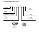
WIRING DIAGRAMS Fig.
WIRING DIAGRAMS (CONTINUED) Fig.
WIRING DIAGRAMS (CONTINUED) W BLACK RED COMP V BLUE U FM1 3 Y/G TP DR IV E R B OAR D CN55 CN19 5(6) 3 W BLACK V RED U BLUE CN54 BLUE CN51 CN53 CN33 CN20 RED SV 4-WAY1 BLUE BLUE YELLOW S BLACK CN2 CN1 RED CN3 CN4 HEAT1 Cra nkc ase He ate r BLACK BLUE CN52 CN10 CN22 CN40 CN44 HEAT2 Ba se P an H ea ter CODE COMP CAP1 EEV FM1 PART NAME COMPRESSOR HIGH PRESSURE SWITCH L L-PRO SV PFC INDUCTOR LOW PRESSURE SWITCH 4-WAY VALVE EXHAUST TEMPERATURE SENSOR CONDENSER TEMPERATURE SENSOR OUTDOOR AM
GUIDE SPECIFICATIONS HORIZONTAL DISCHARGE OUTDOOR UNITS Size Range: 3/4 to 3 Ton Nominal Cooling and Heating Capacity Carrier Model Number: 38MA*R PART 1 − GENERAL 1.01 System Description A. Outdoor air−cooled split system compressor sections suitable for on−the−ground, rooftop, wall hung or balcony mounting. Units consist of a rotary compressor, an air−cooled coil, propeller−type draw−through outdoor fan, reversing valve (HP), accumulator (HP units), metering device(s), and a control box.
Copyright 2016 CAC/BDP D 7310 W. Morris St. D Indianapolis, IN 46231 Edition Date: 01/16 Manufacturer reserves the right to change, at any time, specifications and designs without notice and without obligations.