
Manual
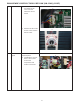
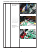
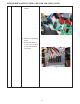
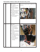
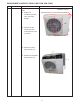
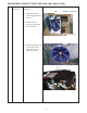
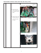
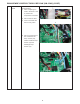
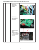
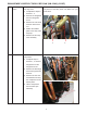
Table Of Contents
- SAFETY CONSIDERATIONS
- INTRODUCTION
- MODEL/SERIAL NUMBER NOMENCLATURES
- SPECIFICATIONS
- DIMENSIONS
- CLEARANCES
- ELECTRICAL DATA
- WIRING
- CONNECTION DIAGRAMS
- WIRING DIAGRAMS (COOLING ONLY)
- WIRING DIAGRAMS (HEAT PUMP)
- REFRIGERATION CYCLE DIAGRAMS
- REFRIGERANT LINES
- SYSTEM EVACUATION and CHARGING
- TROUBLESHOOTING
- OUTDOOR UNIT DIAGNOSTIC GUIDES
- PCB DIAGRAMS
- DIAGNOSIS and SOLUTION
- EEPROM Parameter Error Diagnosis and Solution (E0/F4)
- Indoor / outdoor unit's communication diagnosis and solution (E1)
- Zero crossing detection error diagnosis and solution (E2)
- Fan speed has been out of control diagnosis and solution (E3/F5)
- Index 1
- Open circuit or short circuit of temperature sensor diagnosis and solution (E4/E5/F1/F2/F3)
- Refrigerant Leakage Detection diagnosis and solution (EC)
- Overload current protection diagnosis and solution (F0)
- IPM malfunction or IGBT over-strong current protection diagnosis and solution (P0)
- Over voltage or too low voltage protection diagnosis and solution (P1)
- High temperature protection of compressor top diagnosis and solution (P2)
- Inverter compressor drive error diagnosis and solution (P4)
- Main Parts Check
- Compressor Checking
- IPM Continuity Check
- Fan Motor
- Pressure on Service Port
- DISASSEMBLY INSTRUCTIONS Sizes 12K (115V)
- DISASSEMBLY INSTRUCTIONS Sizes 12K (208-230V)
- DISASSEMBLY INSTRUCTIONS Sizes 18K (208-230V)
- DISASSEMBLY INSTRUCTIONS Sizes 24K (208-230V)
- APPENDIX

62
DISASSEMBLY INSTRUCTIONS SIZES 18K (208−230V) (CONT)
2) Pull out the two blue
wires connected to the
four way valve.
3) Remove the
connectors of the
condenser coil temp.
sensor (T3),outdoor
ambient temp. sensor
(T4) and discharge
temp. sensor (T5).
4) Disconnect the
electronic expansion
valve wire.
ƻ
3
ƻ
3
ƻ
4
ƻ
2