
Operator`s manual


CHAPTER 5
FIFTH ECHELON MAINTENANCE
68. Scope of Fifth Echelon Maintenance
The functions allocated to fifth echelon
maintenance level include troubleshooting,
repair, and alignment of modular assem-
blies. Also included is replacement of
parts in the selector mechanism assembly
and in module A10.
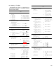
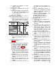
69. Test Equipment and Additional
Equipment Required
a. Test Equipment.
Item
I
Technical
manual
Audio
Oscillator
TS-382F/U
Voltmeter,
Meter
ME-30A/U
Frequenoy
Meter
AN/USM-26
Meter,
Modulation
ME-57/U
Multimeter
ME-26B/U
-------
oscilloscope AN/usM-50A----
R.
F.
Signal
Generator
AN/
URM-25F.
Signal
Generator
AN/URM-46
Radio
Frequency
Wattmeter
AN/URM-43A.
Speotrum
Analyzer
TS-723B/U
RF
Millivoltmeter
411A
Transistor
Power
Supply
721A
b. Additional Equipmen
TM
11-6625-261-12
TM
11-6625-320-12
TM
11-5057
TM
11-6625-400-12
TM
11-6625-200-12
TM
11-5129
TM
11-5551E
TM
11-1257
TM
11-5133
TM
11-5097
t Required.
(1)
(2)
(3)
(4)
(5)
(6)
(7)
Battery cable; a three-conductor
cable of suitable length, with a bat-
tery plug on one end, and a battery
receptacle on the other.
Alignment cover (fig. 28).
ModuIe extender (fig. 27).
Adapter UG-274B/U.
Resistor, 470-ohm, l-watt.
Handset H-138/U.
Dummy antenna (fig. 41).
70. GeneraI
Caution: Refer to the caution notice on
the inside front cover of this manual be-
fore connecting equipment or making tests.
a. The module assembly trouble isola-
tion procedures given in this chapter are
organized to localize and isolate trouble
in defective modules of the RT-505/PRC-
25. A separate procedure is provided for
106
each module. Each procedure, where ap-
plicable, consists of preparation instruc-
tions, test and alignment procedures, and
faulty part isolation information.
b. Rf test signals are unmodulated un-
less otherwise specified. When the fre-
quency of a signal generator is specified
without an accompanying tolerance (an
example of frequency with a tolerance
specified is 29, 950 kc ±5), set the fre-
quency, by using the AN/USM-26, to the
exact number of significant figures desig-
nated.
c. Use a receiver-transmitter (that is
known to be good) as a test set. When work-
ing on a module, remove the cover and
plug the module into the test set. When
alignment is required, replace those cov-
ers that have alignment holes. Use the
module extender (fig, 27) only when di-
rected.
(1).
(2)
(3)
(4)
Remove Battery Box CY-2562/
PRC-25 from the receiver-trans-
mitter case.
Remove the receiver-transmitter
case from the receiver-transmit-
ter.
Connect the battery cable between
Battery, Dry BA-386/PRC-25 (that
is known to be good) and the battery
plug on the receiver-transmitter.
Turn on the test equipment and al-
low a 5-minute warmup period.
Caution: Do not place the re-
ceiver-transmitter in a transmit
condition with a wattmeter con-
nected or an antenna installed.
Waring: The power amplifier
plate voltage is +150 volts dc. Take
all necessary precautions to pro-
tect personnel and test equipment.
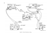
71. Isolating Trouble in Module A1
(fig. 26 and 53)
a. Preparation.
(1) Prepare the following equipment:
(a) Multimeter ME-26B/U.
(b) Handset H-138/U.