
Operator`s manual
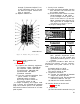
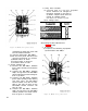
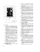
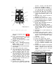

83. Isolating Trouble in Module A14
(fig. 17 and 66)
a. Preparation.
(1) Prepare the following equipment:
(a) Signal Generator AN/URM-48.
(b) Frequency Meter AN/USM-26.
(c) RF Millivoltmeter 411A.
(d) Oscilloscope AN/USM-50A.
(e) Multimeter ME-26B/U.
(i) Module extender.
(2) Remove module A9.
(3) Turn the receiver-transmitter
function switch to ON.
b. VFO InPut Test.
(1)
(2)
(3)
(4)
(5)
Connect the AN/URM-48 between
pin 1 of J2 (receptacle for A9) and
chassis ground. Connect the 411A
across the AN/URM-48 output.
Adjust the AN/URM-48 frequency
to 53 mc and set the level to 10
millivolts, as indicated by the
411A.
Disconnect the 411A from the AN/
URM-48 and connect it between
A14J2 and chassis ground.
Slowly vary the AN/URM-48 fre-
quency from 41 to 65 mc while ob-
serving the 411A.
The 411A should indicate 25 milli-
volts ±2 db throughout the 41- to
65-mc tuned range.
c. 1-Mc Input Test.
(1)
(2)
Connect the AN/USM-26 between
A14J3 and ground. The frequency
meter should indicate 1 mc ±25
Cps .
Connect the AN/USM-50A between
A14J3 and ground. The AN/USM-
50A should indicate 1.5 volts peak-
to-peak.
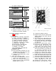
d. Faulty Parts Isolation.
(1)
(2)
Insert the module extender into the
A14 connector and insert A14 into
the module extender. Remove the
cover from A14.
Apply a 53-mc, 0.01-volt signal
between pin A of A14J1 and chassis
ground. Measure the voltages at
the points listed below. Compare
them with the normal signal and dc
voltages listed.
Note: Measure all voltages to ground.
(a) Signal voltage chart.
(b) Dc voltage chart.
Point of measurement
Voltage (de)
J1
PiIl
B
-----------------------
10.0
Q1
emitter
--------------------
6.2
Q1
bsse
-----------------------
6.0
(3) After the replacement of a faulty
part, perform the alignment pro-
cedure outlined in e and f below
and repeat the procedures given in
a, b, and c above. Replace module
A9.
e. Prepration for Alignment.
(1) Set the receiver-transmitter front
panel controls as follows:
(a) BAND switch at 30-52.
(b) Tuning knobs to 30.50 mc.
(c) Function switch at ON.
(2) Remove module A9.
f. Alignment Procedures.
(1)
(2)
(3)
(4)
(5)
(6)
(7)
(8)
Connect the AN/URM-48 between
pin 1 of J6 (receptacle for A9) and
chassis ground. Connect the 411A
across the AN/URM-48 output.
Adjust the AN/URM-48 frequency
to 52 mc and the level to 3 milli-
volts, as indicated by the 411A.
Disconnect the 411A from the AN/
URM-48 and connect it between
A18J2 and chassis ground.
Record the voltage level at A18J2
as indicated by the 411A.
Adjust the AN/URM-48 frequency
to 54 mc (maintain the output level
at 3 millivolts).
Record the voltage level at A18J2
as indicated by the 411A.
Compare the indications obtained
in the procedures given in (4) and
(6) above.
If the indications are
equal to each other, alignment of
A14 is accurate. If the indications
are not equal to each other, pro-
ceed to (8) below.
Repeat the procedures given in (1)
130