
Operator`s manual
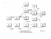
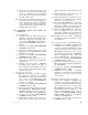

103. Transmitter Test Setup
(fig. 79.8)
a. Plug the test assembly connector into POWER
connector J3 on the front panel of the RT–505/
PRC-25.
b. Connect a test cable No. 7 from ground of
power supply A (2.5 volts) to terminal D of test
assembly terminal board TB1.
c. Connect a test cable No. 7 from the positive
output of power supply A (2.5 volts) to terminal E
of test assembly terminal board TB1.
d. Connect a test cable No. 7 from ground of
power supply B (12.5 volts) to terminal D of test
assembly terminal board TB1.
e. Connect a test cable No. 7 from the positive
output of powersupply B (12.5 volts) to terminal F
of test assembly terminal board TB1.
f. Connect a test cable No.4 from the HP-200AB
audio output to test assembly terminals A and B
(shieId) of terminal board TB1.
g. Connect test cable No. 4 from the ME-30A/U
input to test assembly terminals A and B (shield)
of terminal board TB 1.
h. Connect a test cable No. 2 from coaxial ANT
jack J2 of the RT-505/PRC-25 to the input of the
Attenuator, Adjustable “T”, General Radio Type
GR-874-GA (adjustable attenuator).
i. Connect test cable A
T
O. 3 from the unattenuated
output of the adjustable attenuator to the input
of the AN/URM-43A.
j. Connect a test cable No. 2 from the attenuated
output of the adjustable attenuator to the ME-57/U
input through adapter UG-274/U.
k. Connect test cable 9 from the AN/USM-26
input, through adapter UG-274/U, to the ME-
57/U input.
l. Connect a test cable No. 4 from the ME-57/U
audio output to the TS-723A/U input.
m. Connect a test cable No. 4 from the ME-57/U
audio output to the AN/USM-50A vertical input.
n. Connect a test cable No. 4 from the audio input
terminals to the meter terminals of the TS-723A/U.
o. Do not turn on RT-505/PRC-25. Turn on
all test equipment and allow sufficient warmup
time.
p. Adjust power supply A to 2.5 volts and power
supply B to 12.5 volts.
q. Set the RT-505/PRC-25 function switch to
ON and select a frequency of 41.00 mc. Allow 5
minutes to warmup.
r. Adjust the HP-200AB to 1,000 cps. Adjust the
TRANSMITTER AUDIO INPUT LEVEL control
TAGO 8344-A
on the test assembly and the HP-200AB output
level to produce a 1.4-millivolt reading on the
ME-30A/U.
s. Perform the transmitter system tests indicated
in paragraph 105.
104. Receiver System Tests, Radio Set AN/
PRC-25
a. Sensitivity Test.
(1)
(2)
(3)
(4)
(5)
(6)
Perform the sensitivity test with the
equipment connected in a standard re-
ceiver test setup (para 102 and fig. 79.7),
except set the RF signal level at the RT-
505 /PRC-25 coaxial ANT input to 0.6
microvolt.
Measure the signal-plus-noise-plus-distor-
tion to noise-plus-distortion ratio on the
TS-723A/U, and record. The ratio should
be at least 10 db.
Adjust power supply A to 2.25 volts,
power supply B to 10.0 volts, and repeat
the procedure given in (2) above.
Adjust power supply A to 3.0 volts, power
supply B to 15 volts, and repeat the pro-
cedures given in (2) above.
Repeat the procedures given in (2), (3), and
(4) above at 65 mc.
Repeat the procedure given in (2) above
at 30.00, 52.00, 53.00, and 75.95 mc.
b. Distortion, Audio Power Output, Volume Con-
trol, and Audio Frequency Response Tests.
(1)
(2)
(3)
(4)
(5)
(6)
Perform these tests with the equipment
connected in a standard receiver test
setup (para 102 and fig. 79.7).
Measure the percentage of distortion on
the TS-723A/U. Maximum allowable
distortion is 6 percent.
Adjust the VOLUME control on RT-505/
PRC-25 to produce a 2-volt reading on
the TS-723A/U (used as a vacuum-tube
voltmeter).
Measure the percentage of distortion on
the TS-723A/U.
Maximum allowable
distortion is 10 percent.
Set the VOLUME control on the RT-505/
PRC-25 fully clockwise.
The output
indicated on the TS-723A/U (used as a
vacuum-tube voltmeter) should be at
least 2 volts.
Set the VOLUME control on RT-505/
PRC-25 fully counterclockwise and dis-
connect the RF output cable from the
1066A. The output indicated on the TS-
15