
Operator`s manual


(9)
(l0)
Repeat the procedures given in (7) and
(8) above except increase the RF output
70 db to determine the 70-db-down
points. The 70-db-down points should be
less than 120-kc apart.
Search 50 kc beyond the 70-db-down points
for spurious responses. Detected spurious re-
sponses should not be above the -70-dblevel.
Note.
The receiver system tests are now
completed. Perform the procedures indicated in
paragraph 103 before proceeding.
105. Transmitter System Tests, Radio Set
AN/PRC-25
a. Power Output Test.
(1)
(2)
(3)
(4)
(5)
(6)
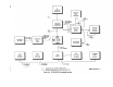
Perform the power output test with the
equipment connected in a standard trans-
mitter test setup (para 103 and fig. 79.8),
except set the HP-200AB output level to
zero and the RT-505/PRC-25 frequency to
30.00 mc.
Set the test assembly TRANSMITTER
CARRIER switch to ON.
Record the frequency and power output
indicated by the AN/USM-26 and AN/
URM-43A respectively.
Set the test assembly TRANSMITTER
CARRIER switch to OFF.
Repeat the procedures given in (2), (3),
and (4) above at 42.00, 52.95, 53.00, 65.00,
and 75.95 mc.
Evaluate the test results.
Minimum
acceptable power output is 1.6 watts on
the low-frequency band (30.00 to 52.95 mc)
and 1.1 watts on the high-frequency band
(53.00 to 75.95 me).
b. Frequency Accuracy Test.
(1)
(2)
(3)
(4)
(5)
Perform the frequency accuracy test with
the equipment connected in a standard
transmitter test setup (para 103 and fig.
79.8), except set the HP-200AB output
level to zero., and the RT-505/PRC-25
frequency to 75.00 mc.
Set the test assembly TRANSMITTER
CARRIER switch to ON.
Record the selected frequency (from the
RT-505/PRC-25 REC-TRANS FRE-
QUENCY indicators) and the output fre-
quency as indicated by the AN/USM-26.
Set the test assembly TRANSMITTER
CARRIER switch to OFF.
Repeat the procedures given in (2), (3),
and (4) above at 75.05, 75.10, 75.20, 73.30,
TAGO 8344-A
(6)
(7)
(8)
(9)
(l0)
75.40, 75.50, 75.60,
mc.
Repeat frequency
75.70, 75.80, and 75.95
check ((5) above) in
reverse order (75.95 mc first).
Turn the megacycles control from 75 to 53,
then back to 75, and repeat the procedures
given in (2), (3), and (4) above.
Return the RT-505/PRC-25 to 75.00 mc,
set power supply A to 2.25 volts, power
supply B to 10.00 volts, and repeat the
procedures given in (2) through (5) above.
Return the RT-505/PRC-25 to 75.00 mc,
set power supply A to 3.0 volts, power
supply B to 15.00 volts, and repeat the
procedures given in (2) through (5) above.
Evaluate the test results.
Maximum
acceptable frequency inaccuracy is ±3.5
kc for all tests.
c. Tone Oscillator Frequency and Modulation Tests.
(1)
(2)
(3)
Perform the tone oscillator frequency and
modulation tests with the equipment con-
nected in a standard transmitter test setup
(para 103 and fig. 79.8) except set the
HP-200AB output level to zero, connect
test cable No. 6 from the AN/USM-26
input to the ME-57/U audio output, and
set the AN/USM-26 for a 10-second count.
Set the test assembly TRANSMITTER
CARRIER switch to ON.
Record the deviation indicated by the
(4)
(5)
ME-57/U and the frequency indicated by
the AN/USM-26.
Set the test assembly TRANSMITTER
CARRIER switch to OFF.
Evaluate the test results.
Acceptable
deviation is 3 kc ±0.5 kc and acceptable
frequency is 150 cps ±1.5 cps (in a 10-
second count).
d. Modulation Capability and Deviation Tests.
(1)
(2)
Perform the modulation capability and
deviation tests with the equipment con-
nected in a standard transmitter test setup
(para 103 and fig. 79.8), except set the
RT-505/PRC-25 frequency to 47.00 mc,
ground A23J3 with test cable No. 1, and
adjust the HP-200AB output (and, as
required, the TRANSMITTER AUDIO
INPUT LEVEL control for a 1.4-millivolt
reading on the ME-30A/U.
Set the test assembly Transmitter
CARRIER switch to ON.
19