
Manual
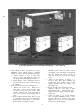

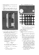

FILTER SECTION OR COMBINATION MIXING
BOX AND FILTER SECTION (All sizes and
arrangements, high and low velocity) — Refer to
Fig. 11.
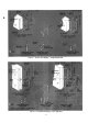
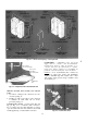
Fig. 11 — Assembly of Acœssory Filter Section or
Combination Mixing Box and Filter Section — (All
Sizes and Arrangements — High-and Low-Velocity)
1. Remove shipping skid.
2. Face air discharge side of accessory toward air
intake side of applicable accessory or cooling
coil section.
3. Fasten support legs to low-velocity filter sec
tion or filter section of combination mixing
box and filter section (sizes 070 thru 120 only)
with two hex head cap screws, plain washers
and nuts per leg.
4. Fasten flange 1 to matching flange of applicable
accessory or cooling coil section with three
(sizes 070 thru 120) or seven (sizes 130 thru
140 — preheat coil section sizes 135 and 140
excluded) 3/8-16 x 3/4-in. hex head cap screws
and matching flange weld nuts.
5. Fasten flange 1 to matching flange of preheat
coil section (sizes 135 and 140) per preceding
steps 5a, 3b, and 3c (substitute flange 1 for
flange 2 in step 5a).
6. Fasten flange 5 to matching flange of applicable
accessory or cooling coil section as follows;
a. Fasten flange 5 (sizes 070 thru 120) with
three 3/8-16 X 3/4-in. hex head cap screws
and matching flange weld nuts.
b. Fasten flange 5 to matching flange of appli
cable accessory or cooling coil section
(preheat coil and cooling coil sections,
sizes 135 and 140 excluded) with seven
3/8-16 X 1-in. hex head cap screws and
matching flange weld nuts.
c. Fasten flange 5 to matching flange of pre
heat coil section (sizes 135 and 140) with
seven 3/8-16 X 1-in. hex head cap screws
and hex nuts.
d. Fasten flange 5 to matching flange of cool
ing coil section (sizes 135 and 140) with
seven 4/4-20 X 1/2-in. self-tapping screws
and matching flange engagement holes.
7. Fasten flanges 2 to matching flanges of appli
cable accessory or cooling coil section with:
three (accessory or cooling coil section —
sizes 070 thru 120); five (accessory or cooling
coil section — size 130) ; five (accessory section
— sizes 135 and 140); or six (cooling coil sec
tion — sizes 135 and 140) 3/8-16 xl-m. hex
head cap screws and hex nuts per two flanges.
8. Tighten all screws securely.
9. Install filter blankoff panels, evenly spaced in
filter tracks, when using high-velocity filters in
low-velocity filter sections or combination
mixing box and filter section to ensure uniform
air distribution.
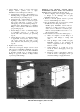
ATOMIZING SPRAY AND STEAM GRID
HUMIDIFIERS — Normally shipped assembled in
unit. If a separate shipment is made, refer to
Installation Instructions provided with humidifier.
Unit Suspension and Mounting
1. Level unit after mounting to insure proper coil
and base pan drainage.
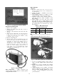
2. Rig and suspend base unit from same points per
Fig. 1. Note that unit sizes 130 and 140 must
be installed on a suspended platform.
3. Rig and suspend accessory combination mixing
box and filter section as follows:
a. Directly fastened to base unit — Rig and
suspend from two top corners on air-intake
end of accessory. Use one suspension rod
per comer.
b. Remote from base unit — Rig and suspend
from four top corners of accessory. Use one
suspension rod per corner.
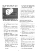
VIBRATION ISOLATORS
1. Arrangement A (unit size 070 thru 140). A
minimum of six isolators should be installed for
proper support — one on each comer of coil
section and one on each comer of air discharge
side of fan section. Two additional isolators
may be installed on air-intake side of fan
section.
2. Arrangements B and D (unit sizes 070 thru
140) and all arrangements (unit sizes 040 thru
060) — Four isolators should be installed for
proper support.
3. Two isolators are required under combination
mixing box and filter section for floor mounting.
4. Vibration isolator hangers are required on combi
nation mixing box and filter section for sus
pended applications per preceding steps 2a and
2b, under “Unit Suspension and Mounting.”
£
14