
Manual


4. Remove protective cover and clean grease from
fan shaft with solvent.
5. Apply a light coat of grease or white lead to fan
shaft.
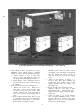
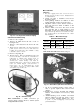
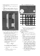
6. Install fan and motor sheaves with correct
angular and parallel alignment per Fig. 22.
Refer to drive package carton for additional
instructions.
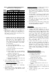
Table 8 — Fan Belt Deflection Force I lb)
Fig. 22 — Correct Sheave Aligrirnent
7. Loosen locknut and adjust belt tension by
turning adjusting screws. Refer to Table 8 for
correct belt tension and note following;
a. Correct belt tension is lowest tension at
which belts will not slip during operation.
b. Correct belt tension may cause belts to slip
and squeal briefly on start-up, which is
normal and will disappear after unit has
reached operating speed. Excessive belt
tension will reduce belt life and may cause
bearing and shaft damage.
c. To determine correct belt tension, use the
following formula for deflection forces
shown in Table 8.
^ ^ Belt Span
Deflection = —rrf-—
64
For a belt span of 16 in., small sheave of
5-in. pitch diameter (PD), size 4L belts:
(1) From formula 1/4-in. deflection
24
BELT
CROSS
SECTION
SMALL
PD
RANGE
DEFLECTION FORCE
- LBS
Std
Befts
Super
Belts
Notch
Belts
Steel Cable
Belts
Min
Max Min Max Min
Max
Min Max
3.0 -3.6
2
2‘6
2Vs
3V4
3
3k
3 k
4
A
3.8 -4.8
2‘/4
3 3
4
3Vs
4k
3k 4k
5.0 -7.0
2‘6
3k
3% 5 3V4
5Vs
4 k
5 k
3.4 -4.3; 2V4
3
3 4
3Vs
4k 4k 5k
B
4.4 -5.6
3
4k
4
5k 4k
6k
5k
7 k
5.8 -8.6
4
6
5V4
7k
6 9
7
8 k
7.0 -9.4
6V2
9
8k
11V4 9V4
13k
Ilk
14
9.6-16.0
8Va I2V4 11 16
12k
18k
14k
17k
2.1 -2.8
IVs
IVs
4L 3.0 -3.5
2Vs
- —
__
—
— -
3.7 -5.0
IVs
2Ve
needed.
(2) From Table 8, deflection force is be
tween 1-7/8 and 2-5/8 lb.
PD — Pitch Diameter
(3)If necessary, increase or decrease the
tension on belts until the deflection
force is between 17/8 and 2 5/8 lb.
8. Secure locknut and check all bolts on motor
base for secureness.
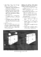
UNIT SIZES 070 THRU 140 -
1. Adjust motor base prior to mounting motor as
follows:
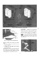
a. Make cardboard pattern showing distance
from base of motor to shaft center per
Fig. 23.
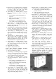
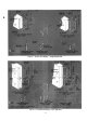
b. Determine specified motor position and
bolt motor base to fan section with hard
ware from accessory drive package per Fig.
24. Do not tighten until sheaves are aligned.
(1) Locate base adjusting slots in respect to
fan shaft as shown.
(2) Place cardboard pattern on motor base.
(3) Check center-to-center distance
between pattern and fan shaft with
center-to-center distance marked on
drive package carton. Required center-
to-center distance should be obtained
with support angle bolts approximately
centered in adjusting slots. This will
permit final adjustment for belt in
stallation and proper tension.
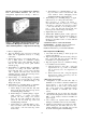
(4) If center-to-center distance is too
short, adjust pivot point upward; if
too long, adjust pivot point down
ward. Refer to Fig. 25.