9-02-2005 15:06 Pagina 1 40DMC GB Y R QUALIT TE SURANC E AS D’S REG OY IS LL INSTALLATION MANUAL ¥ COP_BASE IS O 900 1
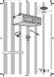
COP_BASE 9-02-2005 15:06 Pagina 2 40DMC GB DUCT MOUNTABLE CEILING UNIT
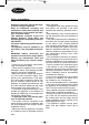
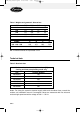
40DMC_GB_install.qxd 27-09-2005 8:49 Pagina 1 ENGLISH ENGLISH DUCT MOUNTABLE CEILING UNIT (cooling and heat pump heating mode only) Contents Safety precautions . . . . . . . . . . . . . . . . . . . . . . . . . . . . . . . . . . . . . . . . . . . . . . Warnings: avoid . . . . . . . . . . . . . . . . . . . . . . . . . . . . . . . . . . . . . . . . . . . . . . . . Weights and dimensions . . . . . . . . . . . . . . . . . . . . . . . . . . . . . . . . . . . . . . . . Technical data . . . . . . . . . . . .
0DMC_GB_install.qxd 27-09-2005 8:49 Pagina 2 Safety precautions Read this instruction manual thoroughly before using the appliance. Keep all installation, operating and maintenance instructions carefully and hand them on if you transfer the appliance to another owner. This appliance conforms to the Low Voltage Directive (73/23 EEC) and Electromagnetic Compatibility Directive (89/336 EEC). It must be installed by qualified personnel only.
40DMC_GB_install.qxd 27-09-2005 8:49 Pagina 3 ENGLISH • All materials used in the manufacture and packing of this appliance are recyclable. • Dispose of packing material and used batteries from the (optional) remote control in compliance with applicable legislation. • This appliance is an air conditioning sys- tem and contains a refrigerant that must be disposed of according to specific procedures.
40DMC_GB_install.qxd 27-09-2005 8:49 Pagina 4 ... in cooling mode, direct entry of sunlight into the room: draw the curtains. ... installing in places near heat sources, which could damage the unit. ... routing the condensate drain pipe to a residential drain or sewer network without a siphon. The height of the siphon in relation to the available head must be such as to allow correct evacuation of condensate. ... loose electrical connections. ...
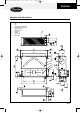
40DMC_GB_install.qxd 27-09-2005 8:49 Pagina 5 ENGLISH Weights and dimensions 1. 2. 3. 4. 5. 6. 7. 8. 9. 10.
40DMC_GB_install.qxd 27-09-2005 8:49 Pagina 6 Table I: Weights and geometric dimensions 40DMC 018 024 028 ØAM 1/4” 1/4” 1/4” ØAN 1/2” 1/2” 5/8” ØAP 21 21 21 kg 32 35 35 036 - 052 060 3/8” 3/8” 3/4” 3/4” 21 21 48 53 40DMC A B C D 018 - 024 - 028 036 - 052 - 060 925 1325 971 1371 865 1265 779 1179 NB: All measurements are expressed in mm.
40DMC_GB_install.
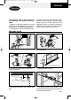
40DMC_GB_install.qxd 27-09-2005 8:49 Pagina 8 Installation SELECTING THE INSTALLATION POSITION • The 40DMC unit is designed ducted installation in suspended ceilings. • The unit must not be accessible to the public. • As a rule, the unit cannot be installed at a height of less than 2.5 m. • It is possible to install the unit at a height of between 2.2 m and 2.5 m from the ground if the system is configured for intake from the rear.
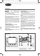
40DMC_GB_install.qxd 27-09-2005 8:49 Pagina 9 ENGLISH INSTALLING THE UNIT Important: the unit must be correctly levelled. Insert the 4 M8 threaded tie rods into the ceiling. Insert the other end of the tie rods through the slots in the hanging brackets on the sides of the unit. Position the antivibration dampers, add the washers and tighten the nuts until the unit is correctly fixed and levelled. If space permits, place a layer of rubber or neoprene between the ceiling and the unit.
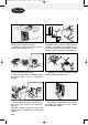
40DMC_GB_install.qxd 27-09-2005 8:49 Pagina 10 It can be configured for intake from below simply by inverting panels A and B. B A When fitting the rear panel, take care not to damage the insulation of the pipes with the edges of the panels. On completion of the operation, fit the filter. A A B During the operation, take the following precautions to avoid damaging parts of the unit: remove the filter.
40DMC_GB_install.qxd 27-09-2005 8:50 Pagina 11 ENGLISH The unit can be predisposed for ducting with circular conduits. Each of the following configurations can be executed with the items supplied with the unit.
40DMC_GB_install.qxd 27-09-2005 8:50 Pagina 12 Do not adopt configurations other than those indicated above, as this may compromise the correct operation of the unit. In particular, avoid operating the unit with just one aperture. After removing the cut-outs, make certain that the insulation covers all the parts in steel sheet. Predisposition of the unit for circular front outlets The unit is supplied with a front enclosure panel with 8” diameter circular cut-outs.
40DMC_GB_install.qxd 27-09-2005 8:50 Pagina 13 ENGLISH 60 mm The area of the panel which can be used for fixing the 8” circular flanges (not supplied) is as shown in the figure. Avoid drilling or fastening screws in the shaded area of the figure so as not to damage the unit’s tray. After removal, make certain that the insulation covers the steel sheet around the cut area. The area which can be used for fixing the 8” circular flanges (not supplied) is as shown in the figure.
40DMC_GB_install.qxd 27-09-2005 8:50 Pagina 14 FRESH AIR INTAKE There is a cut-out on the side of the unit, which can be used as a fresh air intake. It can be opened with a screwdriver. DUCTING Important: the ducting must be designed and calculated by qualified technicians. Determine the dimensions of the ducts according to the air flow rate required and the available static pressure of the unit (refer to the fan diagrams on previous pages).
40DMC_GB_install.qxd 26-09-2005 17:55 Pagina 15 ENGLISH Unit specification graphs Warning! The unit is configured for three speeds, LO-ME-HI. On installations in which it is necessary to set the speed S.HI (see “electrical connections” section), the minimum counter-pressure at the outlet must reach the value shown in the diagrams below (see ★).
40DMC_GB_install.
40DMC_GB_install.
40DMC_GB_install.qxd 27-09-2005 8:50 Pagina 18 Coolant connections Warning! Connect the indoor and outdoor units using copper pipes with flared connections (not supplied). For the lines, use insulated, unwelded, degreased and de-oxidised copper pipe, (Cu DHP type to ISO 1337), suitable for operating pressures of at least 4200 kPa and for a burst pressure of at least 20700 kPa. Copper pipe for hydro-sanitary applications is completely unsuitable.
40DMC_GB_install.qxd 27-09-2005 8:50 Pagina 19 ENGLISH L L The flare must be free from burrs and imperfections. The walls of the flare must be of identical length. Adjustable wrench or torque wrench Indoor side Outdoor side Pipe diameter Lubricate the end of the pipe and the thread of the “FLARE” connection with non-freezing oil. Tighten the union by hand for a few turns and then tighten each connection with two wrenches, to the torque shown in the table. Torque setting mm inches Nm 6.
40DMC_GB_install.qxd 27-09-2005 8:50 Pagina 20 Electrical connections Warning! Powering the unit with an incorrect voltage invalidates the Carrier warranty. Important: • The electrical connection of the system must be made from the outdoor unit. • To make the electrical connections for the unit (cable entry, section of conductors, safety devices, etc.
40DMC_GB_install.qxd 27-09-2005 8:50 Pagina 21 ENGLISH Heat pump heating mode FIG. B 40DMC018, 024, 028, 036, 052,060 NOTES: Refer to the installation manual for the outdoor unit for connection to the mains electricity supply. Interconnection cable (H07RN-F) Interconnection cable (A07RN-F) interconnection between indoor and outdoor unit (mm2) model GND 40DMC018,024,028 40DMC036,052,060 R 3x1 C Y O W2 S V1 V2 V3 V4 40 41 4x1 Not connected CRC 1 2 3 3 x 0.
40DMC_GB_install.qxd 27-09-2005 8:50 Pagina 22 Selecting S.HI speed The unit is configured for three speeds, LO-ME-HI. To select S.HI speed, proceed as follows: • open the cover of the unit’s electrical panel; • move the brown cable from terminal V3 to terminal V4; • close the cover of the electrical panel. Controls Warning! Disconnect the power supply before opening the control unit cover.
40DMC_GB_install.qxd 27-09-2005 8:50 Pagina 23 ENGLISH Alarm code The electronic card contains an internal diagnostic system which supervises the correct operation of the system. When the diagnostic system enters an alarm state, the red LED on the main electronic card flashes as follows: • sequence of flashes of 0.5 seconds ON and 0.5 seconds OFF with an interval of 5 seconds. • The number of flashes varies according to the error diagnosed. Not all errors can be reset (see table below).
40DMC_GB_install.qxd 27-09-2005 8:50 Pagina 24 Maintenance and disposal MAINTENANCE Warning! • The appliance must be maintained and cleaned internally only by qualified personnel. • Always disconnect the appliance from the mains supply before starting any maintenance work and before accessing any internal components. Air filter Check that the filter is clean at least once a month or more frequently if the unit is installed in a dusty environment.
COP_BASE 9-02-2005 GB 15:06 Pagina 3 The manufacturer reserves the right to change any product specifications without notice.
COP_BASE 14-02-2005 9:47 Pagina 4 Via R. Sanzio, 9 - 20058 Villasanta (MI) Italy - Tel 039/3636.