
Owner’s Manual


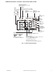


Table Of Contents
- A NOTE ABOUT SAFETY
- GENERAL
- PART NAMES
- INDOOR UNIT DISPLAY INDICATOR
- WIRELESS REMOTE CONTROL
- REMOTE CONTROL
- REMOTE CONTROL FUNCTIONS
- Pressing ON/OFF
- Selecting an Operating Mode
- Setting the Room Temperature Set Point
- Selecting the Fan Speed
- Select the Up-Down Louver Position
- Air Direction
- Auto Swing
- Select Right-Left Direction of the Louver
- Timer Function
- Timer ON Only
- Timer OFF Only
- Timer ON and Timer OFF
- SLEEP Mode
- TURBO Mode
- SELF CLEAN Mode
- FOLLOW ME Mode
- Freeze Protection (FP) Mode
- SILENCE Mode
- LED Light
- Resetting the Remote Control
- Time Delay
- Heating Features
- Auto Defrost Operation
- Auto Start
- Refrigerant Leakage Detection
- CLEANING, MAINTENANCE AND TROUBLESHOOTING
- TROUBLESHOOTING

OM-40MAQ-07 Specifications subject to change without notice. 3
PART NAMES
Fig. 1 — Indoor/Outdoor Unit
INDOOR UNIT DISPLAY INDICATOR
Fig. 2 — Display Panel
1. Front Panel
2. Air Inlet
3. Display
4. Air Filter
5. Right-Left Airflow Grille
6. Up-Down Airflow louver
7. Interconnecting Tubing
8. Control and Power Wiring
to Indoor Unit
9. Service Valves
10. Remote Control
11. Remote Control Bracket
12. Self-Tapping Screws
SELECTED TEMPERATURE
SELF-DIAGNOSTIC CODES INDICATOR
DEFROST INDICATOR
Illuminates when the coil is warming up to prevent
cold blow or when the unit goes into defrost mode.
OPERATION INDICATOR
This indicator flashes once per second after power is
on and illuminates when the unit is in operation.
TIMER INDICATOR
Illuminates during TIMER operation
“ ” when 46°F(8°C) or 54°F(12°C) heating mode is turned on
“ ” for 3 seconds when:
“ ” Displays temperature, operation feature and error codes:
“ ” for 3 seconds when:
• TIMER ON is set
• FRESH, SWING, TURBO, or SILENCE features are turned on
• TIMER OFF is set
“ ” when defrosting
“ ” when unit is self-cleaning