40MBDQ Ducted Style Ductless System Sizes 09 to 58 Installation Instructions TABLE OF CONTENTS PAGE SAFETY CONSIDERATIONS . . . . . . . . . . . . . . . . . . . . . . . . . 2 PARTS LIST . . . . . . . . . . . . . . . . . . . . . . . . . . . . . . . . . . . . . . . 3 SYSTEM REQUIREMENTS . . . . . . . . . . . . . . . . . . . . . . . . . . . 4 WIRING . . . . . . . . . . . . . . . . . . . . . . . . . . . . . . . . . . . . . . . . . . . 4 Fig. 1 − Sizes 09−48 DIMENSIONS . . . . . . . . . . . . . . . . . . . . .
SAFETY CONSIDERATIONS Installing, starting up, and servicing air−conditioning equipment can be hazardous due to system pressures, electrical components, and equipment location (roofs, elevated structures, etc.). Only trained, qualified installers and service mechanics should install, start−up, and service this equipment. Untrained personnel can perform basic maintenance functions such as cleaning coils. All other operations should be performed by trained service personnel.
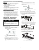
PARTS LIST Table 1 – Parts List PART NAME INDOOR UNIT DRAIN ADAPTER AIR FILTER WIRED CONTROLLER WIRELESS REMOTE LITERATURE PACKAGE INCLUDING INSTALLATION INSTRUCTIONS AND WARRANTY CONDENSATE LIFT PUMP (EXTERNAL SIZES 09-18, INTERNAL SIZES 24-58) Air inlet Electric control cabinet Air filter Drain hose(field supplied) Air outlet O N /O F F FP MODE TIMER ON Refrigerant connecting pipe (field supplied) T E MP TIMER OFF FAN/SLC SLEEP TURBO CLEAN SWING DIRECT LED FOLLOW Fig.
SYSTEM REQUIREMENTS Allow sufficient space for airflow and servicing unit. See Fig. 6 for minimum required distances between the unit and the walls or ceilings. Piping IMPORTANT: Both refrigerant lines must be insulated separately. S Minimum refrigerant line length between the indoor and outdoor units is 10 ft. (3 m). S Table 3 lists the pipe sizes for the indoor unit. Refer to the outdoor unit installation instructions for other allowed piping lengths and refrigerant information.
DIMENSIONS Air inlet from rear side Air filter 4-install hanger Electric control box Outside air intake Test mouth & Test cover 0.98in (25mm) Drain connecting pipe (for lift pump) 0.98in (25mm) Drain pipe Gas connection Liquid connection Airflow Air filter Air inlet from bottom side Airflow Fig.
DIMENSIONS − (CONT) Airflow Airflow Fig.
INSTALLATION CLEARANCES >11.8in(30cm) Strong and durable ceiling >0.8in(2cm) Access Panel >4in(10cm) Ceiling opening size Service access >11.8in(30cm) Ceiling opening size Ceiling > 8.2in(250cm) Right side Left side ( When no ceiling) >0.8in(2cm) Indoor unit Floor Maintenance space Fig.
INSTALLATION LOCATION REQUIREMENTS 5. Secure the unit in position with lock nuts and washers on both sides of the mounting bracket. Ensure the threaded rod does not extend more than 2 in. below the mounting brackets (see Fig. 9). Indoor Unit S Confirm that the ceiling is able to support the weight of the unit. S There should be enough room within the false ceiling for installation and maintenance. S The false ceiling should be horizontal and leveled.
INSTALLING DUCTWORK Connect the return and supply ducts to the duct collars provided on the unit. Adequate distance between the return and supply diffusers should be maintained to avoid short circulation of air within the space. The filter is located on the return side of the unit, on the rear or bottom depending on the return air inlet arrangement. S Condensate piping must not be installed where it may be exposed to freezing temperatures.
(3.) Sizes 24, 36, 48 and 58 have a built−in condensate lift pump. The drain connections (A, B and C) are covered with caps. a. Connect the drainpipe to connector D (see Fig. 21). CONDENSATE DRAIN AND CONDENSATE LIFT PUMP INSTALLATION (HORIZONTAL INSTALLATION) For sizes 9, 12 and 18, the condensate lift pump has been provided in a separate box. Use the following steps to install the External Condensate Lift pump for a Horizontal Installation of the indoor unit.
Remove the cap from connector C and connect the condensate drain pipe to drain connector C. (see Fig. 25). NOTE: For size 18, the External Condensate lift pump should be removed (see Fig. 24). Connector C Fig. 24 − Sizes 9, 12, 18 with External Condensate Lift Pump Connector C Fig. 27 − Check the Bends and Joints for Leakage Fig. 25 − Sizes 24 to 48 with Built−in Condensate Lift Pump DRAINAGE TEST FOR UNITS WITHOUT A CONDENSATE LIFT PUMP Check that the drainpipe is unhindered.
EXTERNAL STATIC PRESSURE Using the KSACN0501AAA Wired Controller, the external static pressure can: S Be manually changed to the fan curves SP2, SP3, SP4. S Choose the Automatic Airflow “AF” adjustment function which will automatically identify the static pressure and regulate the amount of airflow. Follow instructions to configure: 1. Make sure the test run is done with a dry coil. If the coil is not dry, run the unit for 2 hours in FAN ONLY mode to dry the coil. 2.
FAN PERFORMANCES AT VARYING STATIC PRESSURES Table 6 – Static Pressure at the Rated Point and Static Pressure Range Size 9 12 18 24 36 48 58 Units In. WG Pa In. WG Pa In. WG Pa In. WG Pa In. WG Pa In. WG Pa In. WG Pa SP1 0.068 17 0.064 16 0.096 24 0.10 25 0.168 42 0.18 45 .296 74 Static Pressure at Rated Point SP2 SP3 SP4 0.104 0.128 0.176 26 32 44 0.10 0.136 0.20 25 34 50 0.168 0.288 0.392 42 72 98 0.216 0.336 0.528 54 84 132 0.312 0.48 0.62 78 120 155 0.404 0.616 0.64 101 154 160 0.416 .584 0.
FAN PERFORMANCES AT VARYING STATIC PRESSURES (CONT) Fig.
FAN PERFORMANCES AT VARYING STATIC PRESSURES (CONT) Fig.
FAN PERFORMANCES AT VARYING STATIC PRESSURES (CONT) Fig.
FAN PERFORMANCES AT VARYING STATIC PRESSURES (CONT) Fig.
FAN PERFORMANCES AT VARYING STATIC PRESSURES (CONT) Fig.
FAN PERFORMANCES AT VARYING STATIC PRESSURES (CONT) Fig.
FAN PERFORMANCES AT VARYING STATIC PRESSURES (CONT) Fig.
ELECTRICAL DATA Table 8 – Electrical Data UNIT SIZE INDOOR FAN MAX FUSE CB AMP FLA HP W 09 1.11 0.18 130 12 1.11 0.18 130 18 1.2 0.27 200 1.2 0.27 200 36 2.45 0.56 420 48 3.2 0.75 560 58 3.65 0.952 1000 24 V-PH-HZ 208-230/1/60 Refer to outdoor unit installation instructions – Indoor unit powered by the outdoor unit LEGEND FLA - Full Load Amps CONNECTION DIAGRAMS Fig. 39 − Connection Diagrams (sizes 09 to 24) Fig. 40 − Connection Diagrams (sizes 36 and 58) Fig.
h. Apply a small amount of refrigerant oil to the flare connection on the tubing. i. Align center of the pipes and/or service valve. INSTALL ALL POWER, INTERCONNECTING WIRING, AND PIPING TO INDOOR UNIT 1. Run interconnecting piping and wiring from the outdoor unit to the indoor unit. 2. Connect wiring from outdoor unit per the connection diagram (see Fig. 39 and Fig. 40). 3. Replace field wiring cover of the indoor unit. Indoor unit tubing Flare nut Piping A150769 Fig. 46 − Align Pipe Center j.
WIRELESS REMOTE CONTROL INSTALLATION Mounting Bracket (if installed on the wall) 1. Use the two screws supplied with control to attach the mounting bracket to the wall in a location selected by customer and within operating range. 2. Install batteries in the remote control. 3. Place the remote control into the remote control mounting bracket. 4. For remote control operation, refer to the unit owner’s manual.
! CAUTION SYSTEM CHECKS 1. Conceal the tubing where possible. 2. Ensure the drain tube slopes downward along its entire length. 3. Ensure all tubing and connections are properly insulated. 4. Fasten tubes to the outside wall, when possible. 5. Seal the hole through which the cables and tubing pass. UNIT DAMAGE HAZARD Failure to follow this caution may result in equipment damage or improper operation. Never use the system compressor as a vacuum pump.
TROUBLESHOOTING For ease of service, the systems are equipped with diagnostic code display LEDs on both the indoor and outdoor units. The outdoor diagnostic display consists of two LEDs (Red and Green) on the outdoor unit board and is limited to a few errors. The indoor diagnostic display is a combination of flashing LEDs on the display panel or the front of the unit. If possible, always check the diagnostic codes displayed on the indoor unit first.
Copyright 2018 CAC / BDP D 7310 W. Morris St. D Indianapolis, IN 46231 Edition Date: 09/18 Manufacturer reserves the right to change, at any time, specifications and designs without notice and without obligations.