
Installation Instructions


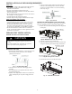


Table Of Contents
- TABLE of CONTENTS
- SAFETY CONSIDERATIONS
- PARTS LIST
- SYSTEM REQUIREMENTS
- WIRING
- DIMENSIONS
- INSTALLATION CLEARANCES
- MAINTENANCE CLEARANCES
- INSTALLATION LOCATION REQUIREMENTS
- INDOOR UNIT INSTALLATION
- Indoor Ducted Unit Installation
- Mounting the Unit
- Return Air Arrangement (Only sizes 09-48)
- Installing DuctWork
- Outside Air Connection
- Condensate Pipe Installation
- Condensate Drain and Condensate Lift Pump Installation (HORIZONTAL INSTALLATION)
- VERTICAL INSTALLATION
- Drainage Test for Units without a Condensate Lift Pump
- Condensate Lift Pump and Drainage Test
- EXTERNAL STATIC PRESSURE
- FAN PERFORMANCES AT VARYING STATIC PRESSURES
- ELECTRICAL DATA
- CONNECTION DIAGRAMS
- START-UP
- TROUBLESHOOTING

10
CONDENSATE DRAIN AND CONDENSATE LIFT
PUMP INSTALLATION (HORIZONTAL
INSTALLATION)
For sizes 9, 12 and 18, the condensate lift pump has been provided in
a separate box. Use the following steps to install the External
Condensate Lift pump for a Horizontal Installation of the indoor unit.
NOTE: Drain connections A, B and C are covered with caps.
(1.) For sizes 09 and 12
a. Remove the cap on the drainage outlet.
b. Cut both ends of the rubber tubing provided into a straight
one.
c. Connect the drainage outlet and condensate lift pump using
the rubber tubing and secure it with clamps on both ends, as
shown on Figure 19.
d. Plug the power cable of the external pump to CN13 /
“PUMP” pin and plug the water level sensor cable to the
CN5 / ”WATER” to enable the pump (see Fig. 23).
(2.) For size 18
a. Remove the cap on drain connector B.
b. Connect the drain connector B and the condensate lift pump
using the L rubber hose and secure it with clamps on both
ends.
c. Connect the drainpipe to the connector D (see Fig. 20).
d. Plug the power cable of the external pump to CN13 /
“PUMP” pin and plug the water level sensor cable to the
CN5 / “WATER” to enable the pump (see Fig. 23).
Fig. 19 − Condensate lift pump installation sizes 09−12
Connector A
Connector B
Connector C
Connector D
Hose
Fig. 20 − Condensate lift pump installation size 18
(3.) Sizes 24, 36, 48 and 58 have a built−in condensate lift pump.
The drain connections (A, B and C) are covered with caps.
a. Connect the drainpipe to connector D (see Fig. 21).
Connector A
Connector B
Connector C
Connector D
Fig. 21 − Connection of drain pipe to condensate lift pump
sizes 24−58
VERTICAL INSTALLATION
Disable the Condensate Lift Pump
The pump must be disabled while the unit is installed vertically (up
flow) or the lift pump assembly is removed from its original
position:
S Open the cover of the E−Parts Box assembly, unplug the “PUMP”
pin to disable the pump function, and short connect the “CN5” plug
to disable the water level sensor (see Fig. 22 and Fig. 23).
Remove
the cover
Short connect the “CN5”
Unplug the “PUMP” plug pin
Fig. 22 − Unplug the PUMP Pin
Fig. 23 − Condensate Lift Pump Connectors