
Installation Instructions

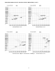
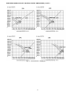


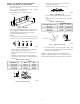
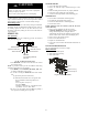

Table Of Contents
- TABLE of CONTENTS
- SAFETY CONSIDERATIONS
- PARTS LIST
- SYSTEM REQUIREMENTS
- WIRING
- DIMENSIONS
- INSTALLATION CLEARANCES
- MAINTENANCE CLEARANCES
- INSTALLATION LOCATION REQUIREMENTS
- INDOOR UNIT INSTALLATION
- Indoor Ducted Unit Installation
- Mounting the Unit
- Return Air Arrangement (Only sizes 09-48)
- Installing DuctWork
- Outside Air Connection
- Condensate Pipe Installation
- Condensate Drain and Condensate Lift Pump Installation (HORIZONTAL INSTALLATION)
- VERTICAL INSTALLATION
- Drainage Test for Units without a Condensate Lift Pump
- Condensate Lift Pump and Drainage Test
- EXTERNAL STATIC PRESSURE
- FAN PERFORMANCES AT VARYING STATIC PRESSURES
- ELECTRICAL DATA
- CONNECTION DIAGRAMS
- START-UP
- TROUBLESHOOTING

21
ELECTRICAL DATA
Table 8 – Electrical Data
UNIT SIZE
INDOOR FAN MAX FUSE CB AMP
V-PH-HZ FLA HP W
Refer to outdoor unit installation instructions –
Indoor unit powered by the outdoor unit
09
208-230/1/60
1.11 0.18 130
12 1.11 0.18 130
18 1.2 0.27 200
24 1.2 0.27 200
36 2.45 0.56 420
48 3.2 0.75 560
58 3.65 0.952 1000
LEGEND
FLA - Full Load Amps
CONNECTION DIAGRAMS
Fig. 39 − Connection Diagrams (sizes 09 to 24)
Fig. 40 − Connection Diagrams (sizes 36 and 58)
Fig. 41 − Control and Power Wiring on Indoor Unit (sizes 09 to 24)
Fig. 42 − Control and Power Wiring on Indoor Unit (sizes 36 to 58)
Notes:
1. Do not use thermostat wire for any connection between indoor and outdoor units.
2. All connections between indoor and outdoor units must be as shown. The connections are sensitive to polarity and will result in a fault code.