
Installation Instructions

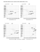
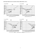


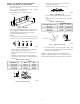
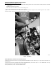
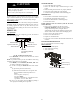


Table Of Contents
- TABLE of CONTENTS
- SAFETY CONSIDERATIONS
- PARTS LIST
- SYSTEM REQUIREMENTS
- WIRING
- DIMENSIONS
- INSTALLATION CLEARANCES
- MAINTENANCE CLEARANCES
- INSTALLATION LOCATION REQUIREMENTS
- INDOOR UNIT INSTALLATION
- Indoor Ducted Unit Installation
- Mounting the Unit
- Return Air Arrangement (Only sizes 09-48)
- Installing DuctWork
- Outside Air Connection
- Condensate Pipe Installation
- Condensate Drain and Condensate Lift Pump Installation (HORIZONTAL INSTALLATION)
- VERTICAL INSTALLATION
- Drainage Test for Units without a Condensate Lift Pump
- Condensate Lift Pump and Drainage Test
- EXTERNAL STATIC PRESSURE
- FAN PERFORMANCES AT VARYING STATIC PRESSURES
- ELECTRICAL DATA
- CONNECTION DIAGRAMS
- START-UP
- TROUBLESHOOTING

22
INSTALL ALL POWER, INTERCONNECTING
WIRING, AND PIPING TO INDOOR UNIT
1. Run interconnecting piping and wiring from the outdoor
unit to the indoor unit.
2. Connect wiring from outdoor unit per the connection
diagram (see Fig. 39 and Fig. 40).
3. Replace field wiring cover of the indoor unit.
Control box
Fig. 43 − Control Box
4. Connect refrigerant piping and drain line outside of indoor
unit. Complete pipe insulation at flare connection then
fasten the piping and wiring to the wall as required.
Completely seal the hole in the wall.
5. Piping:
c. Cut the pipe, with a pipe cutter, at 90 degrees (see Fig. 44).
d. Remove the service connection, if provided with the unit.
Oblique
DŽ
90
Roughness
Burr
A150767
Fig. 44 − Pipe Cutting
e. Remove all the burrs from the cut cross section of the
pipe avoiding any burrs inside the tubes.
f. Remove the flare nuts attached to the indoor and out-
door units.
g. Install the correct size flare nut onto the tubing and
make the flare connection. Refer to Table 9 for the flare
nut spaces.
Table 9 – Flare Nut Spacing
OUTER DIAM. (mm)
A (mm)
Max. Min.
Ø 1/4"(6.35) 0.05(1.3) 0.03(0.7)
Ø 3/8"(9.52) 0.06(1.6) 0.04(1.0)
Ø 1/2"(12.7) 0.07(1.8) 0.04(1.0)
Ø 5/8"(15.88) 0.09(2.2) 0.08(2.0)
Bar
Copper pipe
Clamp handle
Red arrow mark
Cone
Yoke
Handle
Bar
"A"
A150768
Fig. 45 − Flare Nut Spacing
h. Apply a small amount of refrigerant oil to the flare
connection on the tubing.
i. Align center of the pipes and/or service valve.
Indoor unit tubing Flare nut Piping
A150769
Fig. 46 − Align Pipe Center
j. Connect both the liquid and gas piping to the indoor
unit.
k. Tighten the flare nut using a torque wrench as specified
in Table 10.
Table 10 – Tightening Torque
PIPE DIAMETER INCH (mm)
TIGHTENING TORQUE
Ft-lb N-m
Ø1/4” (6.35) 10 to 13 13.6 to 17.6
Ø3/8” (9.52) 24 to 31 32.5 to 42.0
Ø1/2” (12.7) 37 to 46 50.1 to 62.3
Ø5/8” (15.88) 50 to 60 67.7 to 81.3
Flare nut
Copper tube
A150770
Fig. 47 − Tighten the Flare Nut
6. Connect the drain line. The drain line must not have a trap
anywhere in its length, must pitch downwards, and must be
insulated up to the outside wall.
NOTE: For applications where gravity cannot be used for
drainage, a condensate pump accessory is available. Consult the
condensate pump Installation Instructions for more information.