
Installation Instructions
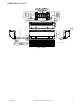


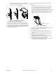
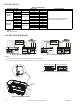
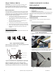
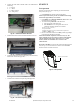
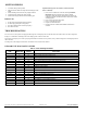
Table Of Contents

12 Specifications subject to change without notice. IM-40MHH-02
ELECTRICAL DATA
Table 5 — Electrical Data
LEGEND
FLA - Full Load Amps
CONNECTION DIAGRAMS
Fig. 18 — Connection Diagram 115V
Fig. 19 — Connection Diagram 230V
NOTES:
1. Do not use thermostat wire for any connection between indoor and outdoor units.
2. All connections between indoor and outdoor units must be as shown. The connections are sensitive to polarity and will result in a fault code.
Fig. 20 — Wiring Diagram Location
Fig. 21 — Control and Power Wiring on the Indoor Unit
HIGH WALL UNIT SIZE INDOOR FAN MAX FUSE CB AMP
V-Ph-Hz FLA HP
Refer to outdoor unit installation instructions –
Indoor unit powered by the outdoor unit
Cooling Only
Models
9K
115-1-60
0.425 0.02
12K 0.425 0.02
9K
208/230-1-60
0.235 0.027
12K 0.235 0.027
18K 0.4 0.037
24K 0.6 0.061
Heat Pump
Models
9K
115-1-60
0.425 0.02
12K 0.47 0.027
9K
208/230-1-60
0.25 0.027
12K 0.34 0.027
18K 0.4 0.037
24K 0.45 0.078
Terminal
block
Wire
cover
Cable
clamp
123 1 2 3
9K and 12K 115V 9K to 24K 208/230V