
Installation Instructions
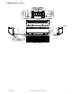


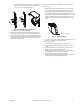
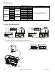
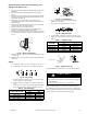
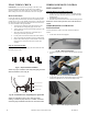
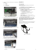
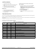
Table Of Contents

IM-40MHH-02 Specifications subject to change without notice. 15
4. Connect the wired remote controller cable to the multi-function
board using:
a. X—Brown
b. Y—Yellow
c. E—Black (ground)
d. 5V—Red (power)
Fig. 32 — Connect the cable to the board
5. Install the multi-function board on the bracket located above the coil.
Fig. 33 — Install the multi-function board
6. Connect the multi-function board to the display board (black cable)
and the main control board (gray cable).
Fig. 34 — Connect the multi-function board
7. Use the ties in the control box to keep the wiring in the right position.
Fig. 35 — Use ties to keep wiring aligned
START-UP
Test Operation
Perform a test operation after completing gas leak and electrical
safety check (see Fig. 36).
1. Push ON/OFF on the remote control to begin testing.
NOTE: A protection feature prevents air conditioner from being
activated for approximately 3 to 4 minutes.
2. Push MODE, select COOLING, HEATING, FAN mode to check
that all functions work correctly.
3. To run the test using MANUAL on the indoor unit:
a. Open front panel of the indoor unit;
b. Push MANUAL once to energize the unit. The set
conditions of manual operation are as follows:
•Preset set point: 76F (24C)
•Fan speed: AUTO
•Discharge air direction: Pre-set position based on operation in
“COOL” or “HEAT” mode.
4. Be sure to set manual switch to the “OFF” position (by pushing it
twice again) after finishing test operation.
NOTE: If the ambient temperature is below 63F (17C). The
remote controller can not be used to turn on the COOL function
when the ambient temperature is below 63F (17C). In this
instance, MANUAL CONTROL can be used to test the
COOL function.
MANUAL CONTROL is located on the right- hand side panel of the
unit (see Fig. 36). Press the button two times to select the COOL
function. Perform a Test Run as normal.
Fig. 36 — Test Operation
Manual control button