
Air Cleaner User Manual
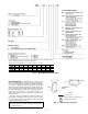
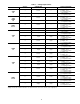
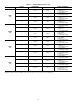


Power Supply and Wiring — Check the unit data
plate to ensure that available power supply matches electri-
cal characteristics of the unit. Provide a disconnect switch of
size required to provide adequate fan motor starting current.
See Tables4-6forunit electrical data.
Install disconnect switch and power wiring in accordance
with all applicable local codes. See Fig. 12-14 and the unit
label diagram. For units with motor sizes less than 5 Hp
(3.7 kW), connect power wiring to unit with no. 10 ring ter-
minal. For units with motor sizes of 5 Hp (3.7 kW) or more,
connect power wiring with
1
⁄
4
-in. ring terminal.
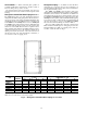
The 40RM, 40RMQ and 40RMS size 007-016 units (ex-
cept 40RM016 with YC or WD option) that have motors wired
for 460-v, 3-ph, 60 Hz operation can be field-converted to
230-v, 3-ph, 60 Hz operation. Rewire the motor according to
the diagram plate on the motor. After reconfiguring the mo-
tor, place the sticker specifying 230-v operation (supplied in
installation packet) over the 460-v sticker on the units cor-
ner post.
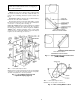
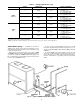
Fan motors are factory installed on all units. Indoor-fan
contactors are located in the fan contactor box behind the
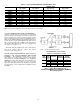
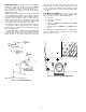
side access panel (see Fig. 12 and 13). Wire the thermostat
to the 24-v control circuit terminal block located in the side
of the fan contactor control box, according to Fig. 14 or the
unit label diagram. If the air handler is part of a split system,
complete the wiring from the condensing unit to the ther-
mostat shown in Fig. 14.
FAN
CONTACTOR
BOX
CONDENSATE
DRAIN
CONNECTION
(HORIZONTAL)
WIRING
ACCESS
COIL
REFRIGERANT/
CHILLED WATER
PIPING ACCESS
CONDENSATE
DRAIN
CONNECTION
(VERTICAL)
MOTOR
AND DRIVE
FAN SCROLL
FILTER
ELEMENTS
FILTER
RETAINER
CLIP
TXV BULB
ACCESS
FAN DRIVE
PULLEY
TXV — Thermostatic Expansion Valve
Fig. 12 — Wiring and Service Access
(Side Panel Removed)
23
22
21
13
12
11
105°C 600V RJ AW
FAN
CONTACTOR
24V
TERMINAL
BLOCK
POWER
WIRING
KNOCKOUT
Fig. 13 — Fan Contactor Box and Terminal Block
(Cover Removed) (Typical)
19