40 RM/RMS 008-034 Packaged Air-Handling Units Concepcion-Carrier Air conditioning Company Philippines Contents INSTALLATION MANUAL, START-UP & SERVICE INSTRUCTIONS Page Safety Considerations 1 Pre-Installation Moving and Storage Rigging 1 1 1 Installation General Uncrating Unit Positioning Unit Isolation Refrigerant and Chilled Water Piping Access Refrigerant Piping Chilled Water Piping Condensate Drain Fan Motor and Drives Power Supply and Wiring Connecting Ductwork 1 1 1 1 2 2 2 3 3 4 4 5 Start
SAFETY CONSIDERATIONS Installation and servicing of air conditioning equipment can be hazardous due to system pressure and electrical components. Only trained and qualified service personnel should install, repair or service air conditioning equipment. Untrained personnel can perform basic maintenance functions such as cleaning coils and cleaning and replacing filters. All operations should be performed by trained service personnel.
Unit Isolation Where extremely quiet operation is essential, install isolators between floor and base of unit or between ceiling and top section of unit. Be sure that unit is level and adequately supported. Use channels at front and sides of unit for reference points when leveling. Refrigerant and Chilled Water Piping Access The 40RM/RMS series units come with stub-out pipes for easy refrigerant and chilled-water piping. These pipes are protruded outside the units for ready installation.
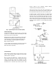
pressure created by fans, preventing complete drainage. Conditions will worsen as filters become dirty. Install clean-out plugs in traps. Pitch drain line downward to an open floor drain or sump. Provide service clearance around drain line to permit removal of panels. Observe all local sanitary codes. As shipped, the unit’s condensate drain pan is not sloped towards the drain connection. The pan slope must be changed to pitch towards the side of the unit with the drain connection. See Fig. 6.
Fig. 7 - Typical 40RMS Chilled Water Piping STRAINER Fan Motor and Drives Motor and drive packages are factory-installed in all units. The standard motor and drive packages consist of the following items : 1 – fan motor 1 – adjustable motor pulley 1 – fan pulley 1 – fan belt for 008-024 sizes; 2 for 028-034 sizes For instructions on changing fan rotation, changing the drive speeds and adjusting drives. Please refer to Fan Rotation Section. Fan motors are factory installed on all units.
Connecting Ductwork Refer to Carrier System Design Manual for the recommended design and layout of ductwork. Fig. 10 shows recommended duct connection to units with two fans. Most unit service can be performed by removing one or both of the unit’s side panels. Coil cleaning or removal or insulation cleaning may require removal of rear, top or bottom panel, depending on the unit’s orientation. When service is completed, replace unit panels. Panels Panels are fastened to unit frame with sheet metal screws.
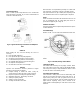
diagram on the inside of the motor terminal box cover for proper reversing procedure. Fig. 14 - Fan Rotation Fig. 12 - Fan Shaft Bearing Individual Fan Wheel Adjustment Loosen the two locking bolts holding the fan wheel hub to the shaft. Position fan wheel in center of the fan housing and tighten locking bolts. Clearance between wheel and housing should be the same on both sides. Fan Belts Motor mounting plate and motor support angles are slotted to permit both vertical and horizontal adjustments.
Condensate Drains Keep condensate drains free of dirt and foreign matter. Return-Air Filters Refer to Replacing Filters Section for filter accessibility and removal. Replace with clean filters of the sizes listed in Tables 1A – 1D. Coil Removal Remove return-air filters. Remove any heavy dirt that may have accumulated on underside of the coil. Coil can be cleaned more easily with a stiff brush, vacuum cleaner or compressed air when coil is dry.
TABLE 1A - 40 RM PHYSICAL DATA - ENGLISH UNIT 4O RM NOMINAL CAPACITY (TONS) OPERATING WEIGHT (lb) Base Unit with TXV FANS Qty… Diam. (in) Nominal Air Flow (cfm) Air flow Range (cfm) Nominal Motor Hp (Standard Motor) 208/230-3-60 and 460-3-60 Motor Speed (rpm) 208/230-3-60 and 460-3-60 REFRIGERANT Operating Charge (lb) (approx per circuit)* DIRECT EXPANSION COIL Max Working Pressure (psig) Face Area (sq ft) No. of Splits No.
TABLE 1B - 40 RMS PHYSICAL DATA - ENGLISH UNIT 4O RMS NOMINAL CAPACITY (TONS) OPERATING WEIGHT (lb) FANS Qty… Diam.
TABLE 4A - ELECTRICAL DATA, STANDARD MOTORS FAN MOTOR UNIT V*-PH-HZ VOLTAGE LIMITS 40RM 008 40RMS 008 40RM 012 40RMS 012 40 RM 016 40 RMS 016 40 RM 024 40 RMS 024 40 RM 028 40 RMS 028 40 RM 034 40 RMS 034 208/230 - 3 - 60 460 - 3 - 60 208/230 - 3 - 60 460 - 3 - 60 208/230 - 3 - 60 460 - 3 - 60 208/230 - 3 - 60 460 - 3 - 60 208/230 - 3 - 60 460 - 3 - 60 208/230 - 3 - 60 460 - 3 - 60 187-253 414 - 528 187 - 253 414 - 528 187 - 253 414 - 528 187 - 253 414 - 528 187 - 253 414 - 528 187 - 253 414 - 528 HP
TABLE 5A - FAN MOTOR DATA, STANDARD MOTOR UNIT 208/230 - 3 - 60 and 460 - 3 - 60 Speed (rpm) Hp Frame Shaft Dia. 40 RM 008 40 RMS 008 40 RM 012 40 RMS 012 40 RM 016 40RMS 016 40RM 024 40 RMS 024 40RM 028 40RMS 028 1725 1.0 2.0 56 Y (NEMA) 7/8" 7/8" 7/8" 40 RM 034 40RMS 034 1745 7.5 132S(IEC) 38 mm 3.0 7/8" TABLE 5B - FAN MOTOR DATA, ALTERNATE MOTOR UNIT 40 RM 008 40 RMS 008 208/230 - 3 - 60 and 460 - 3 - 60 Speed (rpm) Hp Frame Shaft Dia. 2.
TABLE - Standard Drive Data, 60 Hz - English UNIT MOTOR DRIVE Motor Pulley Pitch Diameter (in) Pulley Factory Setting Full Turns Open FAN DRIVE Pulley Pitch Diameter (in) Pulley Bore (in) Belt No. - Section FAN SPEEDS (rpm) Factory Setting Range Max. Allowable Speed (rpm) Max. Full Turns From Closed Position 40RM 40 RMS 008 40RM 40 RMS 012 40RM 40 RMS 016 40RM 40 RMS 024 40RM 40 RMS 028 40RM 40 RMS 034 3.4 - 4.3 3.4 - 4.3 3.4 - 4.3 3.4 - 4.3 3.9 - 5.1 3.9 - 5.1 5 5 4 4 4 4 8.
TABLE - High Static Drive Data, 60 Hz - English UNIT 40RM 40 RMS 008 MOTOR DRIVE Motor Pulley Pitch Diameter (in) 3.4 -4.3 Pulley Factory Setting 5 Full Turns Open FAN DRIVE Pulley Pitch Diameter (in) 6.0* Pulley Bore (in) 1 Belt No. - Section 1 - A41 FAN SPEEDS (rpm) Factory Setting 1121 Range 978 - 1200** Max. Allowable Speed (rpm) 1200 Max. Full Turns From 5.5 Closed Position 40RM 40 RMS 012 40RM 40 RMS 016 40RM 40 RMS 024 40RM 40 RMS 028 40RM 40 RMS 034 3.4 - 4.3 3.4 -4.3 3.4 -4.3 3.9-5.
Table - Fan Performance Data - 0.0 - 0.6 in. wg. ESP - English UNIT 40RM 40RMS 008 40RM 40RMS 012 40RM 40RMS 016 40RM 40RMS 024 40RM 40RMS 028 40RM 40RMS 034 Static Pressure AIRFLOW (CFM) 2,250 2,600 3,000 3,400 3,750 3,000 3,500 4,000 4,500 5,000 4,500 5,300 6,000 6,800 7,500 6,000 7,000 8,000 9,000 10,000 7,500 8,750 10,000 11,250 12,500 9,000 10,500 12,000 13,500 15,000 0.
Table - Fan Performance Data - 0.8 - 1.4 in. wg. ESP - English UNIT 40RM 40RMS 008 40RM 40RMS 012 40RM 40RMS 016 40RM 40RMS 024 40RM 40RMS 028 40RM 40RMS 034 AIRFLOW (CFM) 2,250 2,600 3,000 3,400 3,750 3,000 3,500 4,000 4,500 5,000 4,500 5,300 6,000 6,800 7,500 6,000 7,000 8,000 9,000 10,000 7,500 8,750 10,000 11,250 12,500 9,000 10,500 12,000 13,500 15,000 0.8 RPM 700 732 773 815 855 753 801 853 907 964 725 764 801 847 890 789 844 904 967 1034 710 742 782 827 876 728 774 827 885 947 1.0 BHP 0.
Table - Fan Performance Data - 1.6-2.4 in. wg. ESP - English UNIT 40RM 40RMS 008 40RM 40RMS 012 40RM 40RMS 016 40RM 40RMS 024 40RM 40RMS 028 40RM 40RMS 034 AIRFLOW (CFM) 2,250 2,600 3,000 3,400 3,750 3,000 3,500 4,000 4,500 5,000 4,500 5,300 6,000 6,800 7,500 6,000 7,000 8,000 9,000 10,000 7,500 8,750 10,000 11,250 12,500 9,000 10,500 12,000 13,500 15,000 1.6 RPM 913 940 973 1010 1043 958 998 1042 1089 1138 951 980 1009 1045 1080 999 1042 1091 1143 1200 963 972 991 1019 1053 955 978 1011 1052 - 1.
2.4 BHP 1.94 2.25 2.60 3.70 4.30 4.91 4.
Factory-Supplied Filter Pressure Drop - English Unit 40 RM 40 RMS 008 40 RM 40 RMS 012 40 RM 40 RMS 016 40 RM 40 RMS 024 40 RM 40 RMS 028 40 RM 40 RMS 034 Airflow (Cfm) 2,250 3,000 3,750 3,000 4,000 5,000 4,500 6,000 7,500 6,000 8,000 10,000 7,500 10,000 12,500 9,000 12,000 15,000 Press. Drop (in. wg.) 0.07 0.11 0.15 0.11 0.17 0.23 0.08 0.12 0.17 0.12 0.19 0.26 0.15 0.22 0.30 0.19 0.29 0.
START-UP CHECKLIST (SPLIT SYSTEMS WITH 40RM/RMS UNITS) A. Preliminary Information OUTDOOR: MODEL NO. SERIAL NO: INDOOR : MODEL NO. SERIAL NO: ADDITIONAL ACCESSORIES B. Pre - Start-Up OUTDOOR UNIT Is there any shipping damage? If so, where : (Y/N) Will this damage prevent unit start-up? Check power supply.
CHECK VOLTAGE IMBALANCE Line-to-line Volts AB______ V AC______ V BC______ V (AB + AC + BC)/3 = Average Voltage = ________ V Maximum deviation from average voltage = ________ V Voltage imbalance = 100 x (maximum deviation)/(average voltage) = _______ % If over 2% voltage imbalance, DO NOT ATTEMPT TO START SYSTEM! CALL LOCAL POWER COMPANY FOR ASSISTANCE. C. Start-Up Check evaporator fan speed and record. After at least 10 minutes running time, record the following measurements.