
Specifications


Manufacturer reserves the right to discontinue, or change at any time, specifications or designs without notice and without incurring obligations.
PC 111 Catalog No. 534-80235 Printed in U.S.A. Form 48/50H,P-18SI Pg 1 6-05 Replaces: New
Book1144
Tab 1a1b6a6b
Installation Instructions
Part Number CRECOMZR009E00 and CRECOMZR011E00
CONTENTS
GENERAL ........................................ 1
PACKAGE USAGE AND CONTENTS ..............1
SAFETY CONSIDERATIONS ...................... 2
INSTALLATION ................................. 2-6
CONFIGURATION .............................. 7-9
TROUBLESHOOTING............................10
GENERAL
The accessory economizer package uses microprocessor-
based controls to sequence mechanical cooling with cool out-
door air (free cooling) to satisfy the cooling load and minimize
energy consumption. Free cooling can be used alone or in
conjunction with mechanical cooling.
The standard economizer uses an outdoor-air temperature
sensor to sense outdoor-air temperature. When the outdoor-air
temperature is between two configurable ambient temperatures,
the economizer is allowed to cool. These temperature configura-
tions are the Economizer High Temperature Lockout (ECL.H)
and the Economizer Low Temperature Lockout (ECL.L). The
economizer will provide cooling when the outdoor temperature
is suitable as defined above by the lockout settings and if there is
a cooling demand. In addition, if an outdoor enthalpy sensor
accessory has been installed, then the enthalpy reading must
also be “low” before economizer cooling can occur.
When free cooling is available, the economizer sequences
free cooling with up to three stages of mechanical cooling to
maintain comfort in the space. When free cooling is not avail-
able, the economizer modulates to an adjustable minimum
position to maintain a supply of fresh air entering the building.
Optional barometric relief dampers provide natural building
pressurization control. An optional power exhaust system is
available for jobs requiring greater relief.
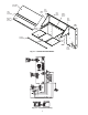
PACKAGE USAGE AND CONTENTS
NOTE: If unit is already equipped with an outdoor air hood, hood
parts in the accessory will not be used and may be discarded.
IMPORTANT: There are two different design revision
48/50HG units currently being produced. Because of
these differences, there are two different versions of
this accessory. This accessory literature covers acces-
sories manufactured for units with design revision 1.
Design revision 0 units are not covered in this acces-
sory book.
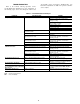
To determine the design revision, refer to the full unit
model number. See Fig. 1 for an example of an HG
model number. The design revision number in the model
number nomenclature is located in position 13.
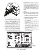
IMPORTANT: Read these instructions completely
before attempting to install the accessory economizer.
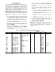
UNIT SIZE PART NO. QTY CONTENTS
48/50PG20-24,
48/50HG014-024
(CRECOMZR009E00)
50TG500495 1 Damper Assy
50TG403161 1 Blockoff
50TG500303 1 Lower Hood Top Panel
50TG500301 1 Hood Side
50TG500302 1 Hood Side
50TG501090 2 Side Filter Guide
50TG500304 1 Upper Hood Top Panel
50TG500306 1 Filter Bracket
50TG501091 1 Filter Retainer Track
KH03DU350 3 Filter
50ZZ401127 1 Control Board
AL56AU130 5 No. 6 Screw
AL48AM307 10
1
/
4
-in. Screw x
5
/
8
-in.
AL31AZ308 25
1
/
4
-in. Screw x
3
/
4
-in.
AS41BZ133 3 Speed Nut
HY76TB110 5 Wire Tie
HY76TB125 1 Wire Tie
50TG402594 1 Harness Assy
— 1 Seal Strip
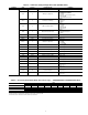
48/50PG28,
48/50HG028
(CRECOMZR011E00)
50TG500496 1 Damper Assy
50TG403163 1 Blockoff
50TG500303 1 Lower Hood Top Panel
50TG500301 1 Hood Side
50TG500302 1 Hood Side
50TG501090 2 Side Filter Guide
50TG500304 1 Upper Hood Top Panel
50TG500306 1 Filter Bracket
50TG501091 1 Filter Retainer Track
KH03DU350 3 Filter
50ZZ401127 1 Control Board
AL56AU130 5 No. 6 Screw
AL48AM307 10
1
/
4
-in. Screw x
5
/
8
-in.
AL31AZ308 22
1
/
4
-in. Screw x
3
/
4
-in.
AS41BZ133 3 Speed Nut
HY76TB110 5 Wire Tie
HY76TB125 1 Wire Tie
50TG402594 1 Harness Assy
— 1 Seal Strip
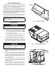
48/50HG014-028
48/50PG20-28
Large Rooftop Units with
COMFORT
LINK™ Controls
Economizer Package Accessory
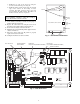
Fig. 1 — Model Number Chart
PositionNo.123456789101112 13 141516
Example:48HGD016AA C 6 1 1 A A
DESIGN REVISION NUMBER