
Specifications


3
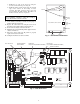
7. Connect the wiring harness (P/N 50TG402594) into the
Economizer Control Board (ECB) plugs J1 and J2 and to
the Main Base Board plugs J2 and J3. See Fig. 7 and 8.
Be sure to connect the plugs with the proper orientation
such that the locking tabs capture the plug.
8. Connect the air quality plug marked “TB2-J10” from the
wiring harness into the TB-J10 plug on the main base
board. Be sure to connect the plug with the proper orien-
tation such that the locking tabs capture the plug.
9. Pass the harness wires through the hole in the control box
and into the return air section. Be sure to secure the wires
so that they will not interfere with any moving parts.
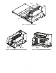
10. Route the wire harness across the frame support as shown
in Fig 9. The motor plug (PL7) should be located at the
actuator side of the unit and snaps into the frame support
bracket. Be careful not to damage the wires. Route the
harness across the back of the top member of the frame as
shown and attach to the frame using the wire ties provided.
11. Connect the motor plug to the plug provided with the
harness. (See Fig. 9.)
12. Install the insulated partition (block-off panel) by sliding
the panel into the unit from the side. The damper side of
the panel will slide along the top of the flange of the
damper assembly, between the return and outdoor air
damper blades. The panel should then be rotated upwards
so that the mounting holes align with the holes in the
panels at the end of the unit. Once in the correct position,
the partition will be horizontal inside the unit as shown in
Fig. 10.
13. Secure the partition to the frame using the screws saved
from Step 3, at the edges of the partition as shown in
Fig. 11.
14. The installation of the damper assembly is now complete.
Units with Outdoor Air Hood:
If the unit was equipped with an outdoor air hood, replace
the outer unit panels using the screws saved from the
earlier steps. Be sure to inspect all panel seals prior to
re-assembly and replace any seals that appear damaged.
Units without Outdoor Air Hood:
If the unit was not equipped with an outdoor air hood,
perform the following procedure to install the hood:
a. Make sure power supply is off.
b. Apply seal strip provided to back flange of both
hood sides where the hood side connects to the unit
back panel. See Fig. 12.
c. Apply seal strip provided to top flange of both
hood sides where hood sides connect to the hood
top panels. See Fig. 12.
d. Install hood sides to the back panels using the
screws provided. The sloped flanges point
outward. The drip edges of the side panels should
face outward as well. The filter guides attach to the
hood sides. The flanges should face inward to hold
the filters in place. See Fig. 12.
e. Apply seal strip along the entire length of the
bottom flange of the hood top. See Fig. 12.
f. Install the bottom part of the hood top using
4 screws provided. See Fig. 12.
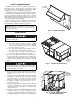
Fig. 5 — Slide Economizer Assembly into Unit
kni
LtrofmoC
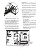
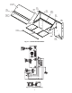
ECONOMIZER
CONTROL BOARD
LOCATION
TB2-J10
Fig. 6 — Unit Control Box