
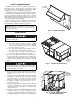
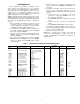
Specifications


7
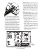
CONFIGURATION
The ComfortLink™ control must be configured for econo-
mizer operation. The default values are for no economizer
and no IAQ accessories installed. These configurations are
changed through the Scrolling Marquee display or a Carrier
network device. The configuration parameters and factory
default values for economizer configuration and indoor air
quality configuration are shown in Tables 1-4.
NOTE: Consult the Controls, Start-Up, Operation, Service and
Troubleshooting Instructions for in-depth instructions on using
and configuring the ComfortLink control. The following instruc-
tions are for the Scrolling Marquee display or Navigator™
accessory.
1. The ComfortLink control must be configured to use the
economizer accessory. A password may be required to
edit the configurations depending on previous settings
configured in the unit. Default password is “1111”.
2. To configure the ComfortLink control, use the arrow keys
to scroll the red LED on the display to the “Configura-
tion” position and press ENTER.
3. Use the arrow keys to scroll down until the display shows
“ECON”. This is the Economizer Configuration sub
mode. Press ENTER.
4. The control will display the Economizer Installed
(EC.EN) setting. Press ENTER once to select the EC.EN
setting for configuration. Press ENTER again for “NO”
to begin flashing.
5. Use the arrow keys to change the configuration from
“NO” to “YES”, then press ENTER and ESCAPE to save
the setting.
6. If additional economizer control accessories have been
added or other configuration parameters are to be
changed from the factory defaults, then repeat the follow-
ing steps:
a. Use the arrow keys to scroll up or down to the
parameter to change. Press ENTER once to select
the setting for configuration.
b. Press ENTER again. The configuration value will
flash.
c. Use the arrow keys to change the configuration
value.
d. Press ENTER and ESCAPE to save the setting.
7. Configuration of the ComfortLink control is now com-
plete. Pressing ESCAPE multiple times will return the
display to the auto-scrolling setting.
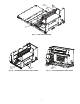
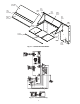
8. Close and secure all access doors.
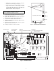
NOTE: The economizer static pressure drop must be
accounted for after installation. See Table 5. Refer to the
Controls and Troubleshooting literature for information on
adjusting the fans.
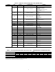
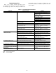
Table 1 — Economizer Configuration Table (48/50PG Units)
LEGEND
FIOP — Factory-Installed Option
ITEM EXPANSION RANGE UNITS
CCN TABLE/
SUB-TABLE
CCN
POINT
DEFAULT
ECON
Economizer Configuration ECON_CFG
→EC.EN Economizer Installed Yes/No ECONO No: no FIOP
Ye s : F I O P
→E.CTL Economizer Control Type 1=Digital, Position Feedback
2=Digital, Command Feedback
3=Analog Control
ECON_CTL 1
→EC.MN Econo Minimum Position 0 to 100 % ECONOMIN 30
→EC MX Econo Maximum Position 0 to 100 % ECONOMAX 100
→H.4M RH Sensor Value at 4mA 0 to 50 % RH_4MA 0
→H.20M RH Sensor Value at 20mA 60 to 100 % RH_20MA 100
→EH.LO Econo Hi Temp Limit 40 to 100 dF OATLECLH 65
→EL.LO Econo Lo Temp Limit –30 to 50 dF OATLECLL 0
→UEFC Unoccupied Free Cooling 0=Disabled
1=Entire Unoccupied Period
2=PreOccupancy Time
UEFC_CFG 2
→FC.TM Free Cool PreOcc Time 1 to 9999 min UEFCTIME 120
→FC.LO Free Cool Low Temp Limit 0 to 70 dF OATLUEFC 50
→PE.EN Power Exhaust Installed Yes/No PE_ENABL No: no FIOP
Ye s : F I O P
→PE.1 PE Stage1 Econo Position 10 to 100 % PE1_POS 40
→PE.2 PE Stage2 Econo Position 10 to 100 % PE2_POS 75
→EN.SW Enthalpy Switch 0=No Switch
1=Normally Open
2=Normally Closed
ENTHLCFG 0: no FIOP
1: FIOP
→E.TRV Economizer Travel Time 5 to 300 sec ECONOTRV 150
→E.MXB Bottom Stage Max Econo 0 to 100 % ECONMAXB50
→E.MXM Middle Stage Max Econo 1 to 100 % ECONMAXM35
→E.MXT Top Stage Max Econo 0 to 100 % ECONMAXT0
→E.DBD Economizer PID Deadband 0 to 25 % ECONBAND 3
→EC.P Economizer PID — kP 0.0 to 99.9 sec ECONO_P2.5
→EC.I Economizer PID — kI 0.0 to 99.9 sec ECONO_I0.1
→EC.D Economizer PID — kD 0.0 to 99.9 sec ECONO_D1
→EC.DT Economizer PID — rate 10.0 to 180.0 sec ECONO_DT 15