48/50AJ,AK,AW,AY020-060 Single Package Large Rooftop Units with Scroll Compressors and COMFORTLINK™ Version 3.X Controls Controls, Start-Up, Operation, Service and Troubleshooting CONTENTS Page SAFETY CONSIDERATIONS . . . . . . . . . . . . . . . . . . . . . . . 2 GENERAL . . . . . . . . . . . . . . . . . . . . . . . . . . . . . . . . . . . . . . .2,3 BASIC CONTROL USAGE. . . . . . . . . . . . . . . . . . . . . . . . 3-6 ComfortLink Control . . . . . . . . . . . . . . . . . . . . . . . . . . . . . .
CONTENTS (cont) SAFETY CONSIDERATIONS Installation and servicing of air-conditioning equipment can be hazardous due to system pressure and electrical components. Only trained and qualified service personnel should install, repair, or service air-conditioning equipment. Untrained personnel can perform the basic maintenance functions of replacing filters. Trained service personnel should perform all other operations.
Table 1 — A Series Product Line UNIT 48AJ 48AK 48AW 48AY 50AJ 50AK 50AW 50AY • Space ventilation control, in Occupied and Unoccupied periods, using CO2 sensors or external signals, with ventilation defined by damper position or ventilation airflow measurement • Smoke control functions • Occupancy schedules • Occupancy or start/stop sequences based on third party signals • Alarm status and history and run time data • Management of a complete unit service test sequence System diagnostics are enhanced by the
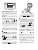
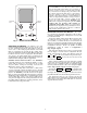
MODE Com NA Run Status Service Test TI M E EWT LW T S E TP Temperature Pressures Setpoints Inputs fort VIG Lin ATO R k 12. 54. 58 44. 6°F 4 4 . 01 ° F °F Alarm Status Outputs Configuration Time Clock ESCAPE MO ENTER Run DE Status Ala rm Servi ce Te Temp Operating Modes Pres sures Setpo ints Inputs Alarms Outpu ENT Accessory Navigator™ Display — The accessory hand-held Navigator display can be used with the 48/50A units. See Fig. 2.
IMPORTANT: The computer system software (ComfortVIEW™, Service Tool, etc.) that is used to interact with CCN controls always saves a template of items it considers as static (e.g., limits, units, forcibility, 24-character text strings, and point names) after the software uploads the tables from a control. Thereafter, the software is only concerned with run time data like value and hardware/force status.
Table 2 — Scrolling Marquee Menu Display Structure RUN STATUS Auto View of Run Status (VIEW) ↓ Econ Run Status (ECON) ↓ Cooling Information (COOL) ↓ SERVICE TEST Service Test Mode (TEST) ↓ Software Command Disable (STOP) ↓ Soft Stop Request (S.STP) ↓ TEMPERATURES PRESSURES SETPOINTS INPUTS OUTPUTS CONFIGURATION Air Temperatures (AIR.T) Air Pressures (AIR.P) Occupied Heat Setpoint (OHSP) General Inputs (GEN.I) Fans (FANS) Unit Configuration (UNIT) Compressor Feedback (FD.
START-UP Controls — Use the following steps for the controls: NOTE: The unit is shipped with the unit control disabled. To enable the control, set Local Machine Disable (Service Test→STOP) to No. 1. Set any control configurations that are required (fieldinstalled accessories, etc.). The unit is factory configured for all appropriate factory-installed options. 2. Enter unit set points. The unit is shipped with the set point default values.
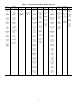
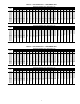
Table 3 — Fan Performance — 48AJ,AK020,025 Units AIRFLOW (Cfm) 4,000 5,000 6,000 7,000 7,500 8,000 9,000 10,000 11,000 12,000 12,500 13,000 AIRFLOW (Cfm) 4,000 5,000 6,000 7,000 7,500 8,000 9,000 10,000 11,000 12,000 12,500 13,000 0.2 Rpm Bhp 394 1.06 388 1.26 427 1.76 476 2.44 502 2.83 527 3.26 580 4.25 633 5.40 687 6.74 741 8.26 768 9.10 796 9.98 2.2 Rpm Bhp 828 4.83 850 5.46 873 6.18 898 7.03 911 7.51 925 8.03 956 9.20 989 10.56 1025 12.10 1063 13.85 1083 14.80 1104 15.81 0.4 Rpm Bhp 413 1.15 448 1.
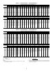
Table 5 — Fan Performance — 48AJ,AK035 Units AIRFLOW (Cfm) 7,000 8,000 9,000 10,000 10,500 11,000 12,000 13,000 14,000 15,000 16,000 17,000 17,500 AIRFLOW (Cfm) 7,000 8,000 9,000 10,000 10,500 11,000 12,000 13,000 14,000 15,000 16,000 17,000 17,500 0.2 Rpm Bhp 549 2.97 606 3.95 664 5.11 723 6.46 753 7.22 783 8.02 843 9.79 903 11.78 964 14.00 1025 16.46 1086 19.17 1147 22.13 1177 23.71 0.4 Rpm Bhp 598 3.40 651 4.40 706 5.58 762 6.96 790 7.73 819 8.55 877 10.34 935 12.35 994 14.60 1053 17.08 1112 19.
Table 7 — Fan Performance — 48AJ,AK050 Units AIRFLOW (Cfm) 8,000 9,000 10,000 11,000 12,000 13,000 14,000 15,000 16,000 17,000 18,000 19,000 20,000 AIRFLOW (Cfm) 8,000 9,000 10,000 11,000 12,000 13,000 14,000 15,000 16,000 17,000 18,000 19,000 20,000 0.2 Rpm Bhp 512 2.98 561 3.90 611 5.00 662 6.27 714 7.74 766 9.41 819 11.29 872 13.40 925 15.74 979 18.32 1032 21.15 1086 24.24 1140 27.60 0.4 Rpm Bhp 560 3.38 604 4.33 651 5.45 699 6.75 748 8.24 798 9.93 848 11.84 899 13.96 951 16.32 1003 18.92 1055 21.
Table 9 — Fan Performance — 50AJ,AK020,025 Units AIRFLOW (Cfm) 4,000 5,000 6,000 7,000 7,500 8,000 9,000 10,000 11,000 12,000 12,500 13,000 AIRFLOW (Cfm) 4,000 5,000 6,000 7,000 7,500 8,000 9,000 10,000 11,000 12,000 12,500 13,000 0.2 Rpm Bhp 394 1.06 388 1.26 398 1.59 441 2.18 463 2.52 486 2.90 532 3.76 579 4.76 627 5.91 675 7.23 699 7.96 724 8.72 2.2 Rpm Bhp 815 4.40 834 5.03 853 5.75 874 6.58 885 7.04 897 7.53 922 8.62 950 9.86 980 11.26 1013 12.84 1030 13.69 1048 14.59 0.4 Rpm Bhp 398 1.08 428 1.
Table 11 — Fan Performance — 50AJ,AK035 Units AIRFLOW (Cfm) 7,000 8,000 9,000 10,000 10,500 11,000 12,000 13,000 14,000 15,000 16,000 17,000 17,500 AIRFLOW (Cfm) 7,000 8,000 9,000 10,000 10,500 11,000 12,000 13,000 14,000 15,000 16,000 17,000 17,500 0.2 Rpm Bhp 517 2.72 569 3.59 622 4.63 675 5.84 702 6.51 729 7.23 784 8.80 839 10.57 894 12.54 949 14.73 1005 17.13 1061 19.76 1088 21.16 0.4 Rpm Bhp 568 3.14 616 4.04 665 5.10 716 6.34 741 7.02 767 7.75 819 9.35 872 11.15 925 13.15 979 15.36 1033 17.
Table 13 — Fan Performance — 50AJ,AK050 Units AIRFLOW (Cfm) 8,000 9,000 10,000 11,000 12,000 13,000 14,000 15,000 16,000 17,000 18,000 19,000 20,000 AIRFLOW (Cfm) 8,000 9,000 10,000 11,000 12,000 13,000 14,000 15,000 16,000 17,000 18,000 19,000 20,000 0.2 Rpm Bhp 485 2.76 530 3.62 577 4.62 625 5.80 673 7.15 722 8.69 771 10.43 821 12.37 870 14.52 920 16.89 971 19.50 1021 22.35 1071 25.43 0.4 Rpm Bhp 532 3.15 574 4.03 617 5.06 661 6.26 707 7.63 753 9.19 800 10.95 848 12.91 896 15.08 945 17.48 994 20.
Table 15 — Fan Performance — 48AW,AY020,025 Units AIRFLOW (Cfm) 4,000 5,000 6,000 7,000 7,500 8,000 9,000 10,000 11,000 12,000 12,500 13,000 AIRFLOW (Cfm) 4,000 5,000 6,000 7,000 7,500 8,000 9,000 10,000 11,000 12,000 12,500 13,000 0.2 Rpm Bhp 394 1.06 394 1.29 445 1.87 498 2.59 526 3.02 554 3.48 610 4.55 668 5.80 727 7.25 786 8.90 816 9.81 846 10.77 0.4 Rpm Bhp 422 1.20 461 1.66 505 2.26 553 3.01 578 3.45 604 3.93 657 5.03 711 6.31 766 7.79 823 9.48 852 10.40 880 11.38 0.6 Rpm Bhp 486 1.56 520 2.
Table 17 — Fan Performance — 48AW,AY035 Units) AIRFLOW (Cfm) 7,000 8,000 9,000 10,000 10,500 11,000 12,000 13,000 14,000 15,000 16,000 17,000 17,500 AIRFLOW (Cfm) 7,000 8,000 9,000 10,000 10,500 11,000 12,000 13,000 14,000 15,000 16,000 17,000 17,500 0.2 Rpm Bhp 568 3.13 629 4.17 690 5.40 753 6.85 784 7.65 816 8.50 879 10.39 943 12.51 1007 14.89 1072 17.52 1136 20.41 1201 23.58 1233 25.27 0.4 Rpm Bhp 616 3.56 673 4.62 731 5.88 790 7.35 820 8.16 851 9.03 912 10.94 973 13.09 1036 15.48 1098 18.13 1162 21.
Table 19 — Fan Performance — 48AW,AY050 Units AIRFLOW (Cfm) 8,000 9,000 10,000 11,000 12,000 13,000 14,000 15,000 16,000 17,000 18,000 19,000 20,000 AIRFLOW (Cfm) 8,000 9,000 10,000 11,000 12,000 13,000 14,000 15,000 16,000 17,000 18,000 19,000 20,000 0.2 Rpm Bhp 536 3.18 588 4.17 642 5.35 696 6.72 751 8.29 807 10.09 863 12.12 919 14.38 975 16.90 1032 19.67 1089 22.71 1146 26.04 1203 29.65 0.4 Rpm Bhp 582 3.58 630 4.60 680 5.80 732 7.20 784 8.80 837 10.62 891 12.67 946 14.96 1000 17.49 1056 20.
Table 21 — Fan Performance — 50AW,AY020,025 Units AIRFLOW (Cfm) 4,000 5,000 6,000 7,000 8,000 9,000 10,000 11,000 12,000 13,000 14,000 15,000 AIRFLOW (Cfm) 4,000 5,000 6,000 7,000 8,000 9,000 10,000 11,000 12,000 13,000 14,000 15,000 0.2 Rpm Bhp 394 1.06 388 1.26 421 1.72 471 2.38 522 3.19 575 4.16 629 5.30 683 6.62 739 8.12 794 9.82 850 11.73 906 13.85 0.4 Rpm Bhp 409 1.13 445 1.57 485 2.12 528 2.80 573 3.64 621 4.63 671 5.79 723 7.14 776 8.67 829 10.40 883 12.34 938 14.48 0.6 Rpm Bhp 473 1.47 504 1.
Table 23 — Fan Performance — 50AW,AY035 Units AIRFLOW (Cfm) 7,000 8,000 9,000 10,000 10,500 11,000 12,000 13,000 14,000 15,000 16,000 17,000 17,500 AIRFLOW (Cfm) 7,000 8,000 9,000 10,000 10,500 11,000 12,000 13,000 14,000 15,000 16,000 17,000 17,500 0.2 Rpm Bhp 537 2.87 592 3.81 648 4.91 705 6.20 734 6.92 762 7.69 821 9.38 879 11.28 938 13.40 997 15.75 1057 18.34 1116 21.17 1146 22.68 0.4 Rpm Bhp 588 3.31 638 4.27 691 5.40 744 6.71 771 7.44 799 8.22 854 9.93 911 11.85 968 13.99 1025 16.36 1083 18.
Table 25 — Fan Performance — 50AW,AY050 Units AIRFLOW (Cfm) 8,000 9,000 10,000 11,000 12,000 13,000 14,000 15,000 16,000 17,000 18,000 19,000 20,000 AIRFLOW (Cfm) 8,000 9,000 10,000 11,000 12,000 13,000 14,000 15,000 16,000 17,000 18,000 19,000 20,000 0.2 Rpm Bhp 509 2.95 558 3.87 608 4.96 659 6.23 710 7.68 763 9.35 815 11.22 868 13.31 921 15.64 974 18.20 1028 21.01 1081 24.08 1135 27.42 0.4 Rpm Bhp 555 3.35 600 4.29 646 5.40 694 6.69 743 8.17 793 9.86 843 11.75 895 13.86 946 16.21 998 18.79 1050 21.
Table 27 — Motor Limitations Nominal Maximum Bhp 5 BkW 3.73 7.5 5.6 10 7.46 15 11.19 20 14.92 25 18.65 30 22.38 40 29.84 Bhp 5.9 8.7 9.5 10.2 11.8 15.3 18.0 22.4 23.4 28.9 29.4 35.6 34.7 42.0 Nominal Bhp 5 BkW 3.73 7.5 5.6 10 7.46 15 11.19 20 14.92 25 18.65 30 22.38 40 29.84 Bhp 5.9 8.7 9.5 10.2 11.8 15.3 18.0 22.4 23.4 28.9 29.4 35.6 34.7 42.0 HIGH-EFFICIENCY MOTORS Maximum Amps BkW 230 v 460 v 4.40 14.6 7.9 6.49 22 — 7.09 — 12.0 7.61 28 — 8.80 — 14.6 11.41 43.8 — 13.
10. Under the Configuration→CCN→SC.OV submenu, the following schedules and overrides should be configured: CONTROLS QUICK START The following section will provide a quick user guide to setting up and configuring the A series units with ComfortLink™ controls. See Basic Control Usage section on page 3 for information on operating the control. O.T.L. SPT.O T58.
Multi-Stage Constant Volume Units with Mechanical Thermostat — To configure the unit, per- 10. See the Economizer Options section below for addition economizer option configurations. 11. See the Exhaust Options section below for addition exhaust option configurations. form the following: 1. The unit is shipped with the unit control disabled. Enable the control by setting Local Machine Disable (Service Test→STOP) to No. 2. Under Configuration→UNIT→C.TYP, set C.TYP to 3 (TSTAT MULTI). 3.
UP or DOWN key to display the correct value for hours, in 24-hour (military) time. Press ENTER and hour value is saved and the minutes digits will start flashing. Use the same procedure to display and save the desired minutes value. 5. Configure the unoccupied time for period 1 (UNC). Press ENTER to go into Edit mode, and the first two digits of the 00.00 will start flashing. Use the UP or DOWN key to display the correct value for hours, in 24-hour (military) time.
Table 29 — Service Test ITEM TEST STOP S.STP FAN.F F.4.CH INDP ECN.C E.PWR E.CAL PE.A PE.B PE.C H.I.R ALRM FANS S.FAN S.VFD CD.F.A CD.F.B COOL A1 A2 MLV B1 B2 HEAT HT.1 HT.2 HT.3 HT.4 HT.5 HT.6 EXPANSION Service Test Mode Local Machine Disable Soft Stop Request Supply Fan Request 4 in. Filter Change Mode TEST INDEPENDENT OUTPUTS Economizer Act.Cmd.Pos.
VFD Control — On VFD equipped supply fans, supply The state of the input on the display can be found at Inputs→AIR.Q→IAQ.I. Before configuring the switch functionality, first determine how the switch will be read. A closed switch can indicate either a low IAQ condition or a high IAQ condition. This is set at Configuration→SW.LG and IAQ.L. The user can set what a low reading would mean based on the type of switch being used. Setting IAQ.L to OPEN means that when the switch is open the input will read LOW.
mode. The System mode is the top level mode that defines three essential states for the control system: OFF, RUN and TEST. The HVAC mode is the functional level underneath the System mode which further defines the operation of the control. The Control mode is essentially the control type of the unit (Configuration→UNIT→C.TYP). This defines from where the control looks to establish a cooling or heating mode and whether 2 stages or multiple stages of cooling capacity operation are controlled.
HVAC Mode — COMP.STUCK ON — The unit is shut down because there is an indication that a compressor is running even though it has been commanded off. HVAC Mode — TEST — The unit is in the self test mode which is entered through the Service Test menu. HVAC Mode — VENT — This is a normal operation mode where no heating or cooling is required and outside air is being delivered to the space to control IAQ levels. HVAC Mode — HIGH COOL — This is a normal cooling mode where a high cooling demand is required.
System Mode = OFF? No FireSmoke Control System Mode Yes Inputs -> FIRE -> FSD in alarm? No HVAC Mode = OFF (Disabled) Unit not in factory test AND fire-smoke control mode is alarming? No Yes Inputs -> FIRE -> PRES in alarm? Yes No Inputs -> FIRE -> EVAC in alarm? Yes HVAC Mode = OFF (Fire Shutdown) No Yes HVAC Mode = OFF (Pressurization) HVAC Mode = OFF (Evacuation) HVAC Mode = OFF (Purge) Exceptions Config->UNIT-> C.
Unit Configuration Submenu — The UNIT sub- The sensors and configurations that automatically turn on this board are: Configuration→UNIT→SFS.M = 1 (Supply Fan Status Switch Monitoring) Configuration→UNIT→SENS→SP.RS = Enable (Static Pressure Reset Sensor Enable) Configuration→EDT.R→RES.S = Enable (4 to 20 mA Supply Air Reset Sensor Enable) Configuration→DMD.L→DM.L.S = 1 (2 SWITCHES) (Demand Limiting using 2 discrete switches) Configuration→DMD.L→DM.L.
Table 31 — Unit Configuration ITEM UNIT C.TYP CV.FN RM.CF CEM TCS.C TCS.H SFS.S SFS.M VAV.S SIZE DP.XR MAT.S MAT.R ALTI SENS SPT.S SP.O.S SP.O.R RRH.S FLT.S SP.RS EXPANSION UNIT CONFIGURATION Machine Control Type Fan Mode (0=Auto, 1=Cont) Remote Switch Config CEM Module Installed Temp.Cmp.Strt.Cool Factr Temp.Cmp.Strt.Heat Factr Fan Fail Shuts Down Unit Fan Stat Monitoring Type VAV Unocc.Fan Retry Time Unit Size (20-60) Discharge Press. Transducers MAT Calc Config Reset MAT Table Entries? Altitude……..
changed. The configurations are provided in case a field replacement of a board occurs and the settings are not preserved by the download process of the new software. The following configurations apply to all machine control types (C.TYP) except 4 and 6. These configurations are located at the local display under Configuration→UNIT. See Table 32. There are either three or four compressors divided among two refrigeration circuits in the unit. Circuit A always contains two compressors (A1,A2).
Table 33 — Setpoints ITEM OHSP OCSP UHSP UCSP GAP V.C.ON V.C.OF SASP SA.HI SA.LO SA.HT T.PRG T.CL T.V.OC T.V.UN EXPANSION Occupied Heat Setpoint Occupied Cool Setpoint Unoccupied Heat Setpoint Unoccupied Cool Setpoint Heat-Cool Setpoint Gap VAV Occ. Cool On Delta VAV Occ. Cool Off Delta Supply Air Setpoint Supply Air Setpoint Hi Supply Air Setpoint Lo Heating Supply Air Setpt Tempering Purge SASP Tempering in Cool SASP Tempering Vent Occ SASP Tempering Vent Unocc.
sensor control types (C.TYP=5 and 6) in both the occupied and unoccupied periods. This section is devoted to the process of cooling mode determination for the three types outlined above. VAV Cool Mode Selection during the Occupied Period (C.TYP = 1,2 and Operating Modes→MODE→OCC =ON) — There is no difference in the selection of a cooling mode for either VAV-RAT or VAV-SPT in the occupied period.
Demand Level Low Cool Off Offset (L.C.OF) — This is the cooling set point offset subtracted from “cooling set point plus L.C.ON” at which point a Low Cool mode ends. NOTE: The “high cool end” trip point uses the “low cool off” (L.C.OF) offset divided by 2. To enter into a LOW COOL mode, the controlling temperature must rise above [the cooling set point plus L.C.ON.] To enter into a HIGH COOL mode, the controlling temperature must rise above [the cooling set point plus L.C.ON plus H.C.ON.
3 compressor unit, if no compressors are currently on, compressor A2 is currently under a minimum off compressor timeguard, and 2 compressors are to be turned on, then compressors A1 and B1 will be turned on immediately instead of A1 and A2. Low Cool Versus High Cool Mechanical Staging — The number of compressors to be requested during a cooling mode are divided into 2 groups by the control, HVAC mode = Lo Cool and HVAC mode = Hi Cool.
Table 37 — 2-Stage Sequence — 48/50AJ,AW020-027 EDT Low Override — There is an override if EDT drops too low based on an alert limit that will lock out cooling. If the supply air/evaporator discharge temperature (EDT) falls below the alert limit (Configuration→ALLM→SA.L.O) cooling will be inhibited. There is a 20-minute hold off on starting cooling again once the following statement is true: EDT minus (Run Status→COOL→SUMZ→ADD.R) has risen above SA.L.O. The variable ADD.
Table 41 — Staging Sequence Without Hot Gas Bypass — 48/50AK,AY030-060 and Multi-Stage 48/50AJ,AW030-060 STAGE 0 1 COMP A1 A2 B1 B2 OFF OFF OFF OFF ON OFF OFF OFF 30 35 40 50 60 0% 0% 0% 0% 0% 23% 22% 21% 23% 24% SEQUENCE 1 2 3 Compressor Status ON OFF ON ON OFF ON OFF OFF Unit Capacity 48/50A 45% 50% 48% 52% 43% 50% 46% 46% 50% 50% 4 5 0 1 ON ON ON OFF ON ON ON ON OFF OFF OFF OFF OFF ON OFF ON 73% 74% 71% 68% 74% 100% 100% 100% 100% 100% 0% 0% 0% 0% 0% 23% 26% 21% 23% 26% SEQUENCE 2 2
Table 44 — Run Status Cool Display ITEM COOL C.CAP CUR.S MAX.S DEM.L SUMZ SMZ ADD.R SUB.R R.PCT Y.MIN Y.PLU Z.MIN Z.PLU H.TMP L.TMP PULL SLOW EXPANSION COOLING INFORMATION Current Running Capacity Current Cool Stage Maximum Cool Stages Active Demand Limit COOL CAP.
Reset MAT Table Entries? (MAT.R) — This configuration allows the user to reset the internally stored MAT learned configuration data back to the default values. The defaults are set to a linear relationship between the economizer damper position and OAT and RAT in the calculation of MAT. SumZ Overrides — There are a number of overrides to the SumZ algorithm which may add or subtract stages of cooling. • High Temp Cap Override (H.TMP) • Low Temp Cap Override (L.
Table 45 — Demand Limit Configuration ITEM DMD.L DM.L.S D.L.20 SH.NM SH.DL SH.TM D.L.S1 D.L.S2 EXPANSION DEMAND LIMIT CONFIG. Demand Limit Select Demand Limit at 20 ma Loadshed Group Number Loadshed Demand Delta Maximum Loadshed Time Demand Limit Sw.1 Setpt. Demand Limit Sw.2 Setpt. RANGE 0-3 0 - 100 0 - 99 0 - 60 0 - 120 0 - 100 0 - 100 Run Status→COOL→DEM.L = 1 100% Configuration→DMD.L→D.L.S1 Configuration→DMD.L→D.L.S2 Configuration→DMD.L→D.L.S2 4-20 mA Demand Limiting (DM.L.
Head Pressure Control Operation — The following logic describes the head pressure control routine when any compressor has been commanded on. When the compressor has been commanded on, then condenser fan A will be energized (CD.F.A = ON). If the highest active circuit SCT is above the HPSP, then condenser fan B will be energized (CD.F.B = ON). If the OAT is above 75 F, then both condenser fans A and B will be energized (CD.F.A = ON and CD.F.B = ON).
(Configuration→HEAT→OC.EN). See descriptions above in the Setting Up the System section for more information. If the unit is allowed to select a heat mode, then the next step is an evaluation of demand versus set point. At this point, the logic is the same as for control types SPT Multi-Stage and SPT-2 Stage, (C.TYP = 5,6) except for the actual temperature compared against set point. See Temperature Driven Heat Mode Evaluation section. Tstat-Multi-Stage (C.TYP = 3) and Tstat-2 Stage (C.
Table 48 — Heat/Cool Set Point Offsets ITEM D.LV.T L.H.ON H.H.ON L.H.OF L.C.ON H.C.ON L.C.OF C.T.LV H.T.LV C.T.TM H.T.TM EXPANSION COOL/HEAT SETPT. OFFSETS Dmd Level Lo Heat On Dmd Level(+) Hi Heat On Dmd Level(-) Lo Heat Off Dmd Level Lo Cool On Dmd Level(+) Hi Cool On Dmd Level(-) Lo Cool Off Cool Trend Demand Level Heat Trend Demand Level Cool Trend Time Heat Trend Time RANGE -1 - 2 0.5 - 2.0 0.5 - 2 -1 - 2 0.5 - 2 0.5 - 2 0.1 - 5 0.
HT.CF = 3 (Staged Gas Heating Control) — As an option, the units with gas heat can be equipped with staged gas heat controls that will provide from 5 to 11 stages of heat capacity. This is intended for tempering mode and tempering economizer air when in a cooling mode and the dampers are fully closed. Tempering can also be used during a preoccupancy purge to prevent low temperature air from being delivered to the space. Tempering for staged gas will be discussed in its own section.
units there will be one IGC board. On size 030-050 high heat units and 060 low heat units there are two IGC boards. On size 060 high heat units there are three IGC boards. When a call for gas heat is initiated, power is sent to W on the IGC boards. For standard 2-stage heat, all boards are wired in parallel. For staged gas heat, each board is controlled separately. When energized, an LED on the IGC board will be turned on. See Table 56 for LED explanations.
Table 53 — Staged Gas Heat Control Steps (Configuration→Heat→ SG.CT→HT.
Table 56 — IGC LED Indicators LED INDICATION On Off 1 Flash 2 Flashes 3 Flashes 4 Flashes 5 Flashes 6 Flashes 7 Flashes 8 Flashes 9 Flashes • The unit just went into occupied mode and there has been no cooling mode yet and a heat cycle occurs or was in progress when the unit went occupied. In both cases, if and when the heat mode terminates, a heat cycle has occurred and any subsequent heat cycles will not be treated as a morning warm up period.
Table 57 — Static Pressure Control Configuration ITEM SP SP.CF SP.FN SP.S SP.LO SP.HI SP.SP SP.MN SP.MX SP.FS S.PID SP.TM SP.P SP.I SP.D SP.SG TEXT DESCRIPTION SUPPLY STATIC PRESS.CFG. Static Pres. VFD Control? Static Pres. Fan Control? Static Pressure Sensor Static Press. Low Range Static Press. High Range Static Pressure Setpoint VFD Minimum Speed VFD Maximum Speed VFD Fire Speed Override STAT.PRESS.PID CONFIGS Static Press. PID Run Rate Static Press. Prop. Gain Static Press. Intg. Gain Static Press.
conditions. For example, a system design requirement may be 1.2 in. wg, the equipment may be capable of providing 3.0 in. wg and the supply duct is designed for 5.0 in. wg. In this case, the installer could enter 3.0 in. wg as the supply static pressure set point and allow the air terminal system to dynamically adjust the supply duct static pressure set point as required.
Table 60 — Dirty Filter Switch Points Fan Status Monitoring GENERAL — The A Series ComfortLink™ controls offer the capability to detect a failed supply fan through either a duct static pressure transducer or an accessory discrete switch. The fan status switch is an accessory that allows for the monitoring of a discrete switch, which trips above a differential pressure drop across the supply fan.
Table 61 — Economizer Configuration Table ITEM EC.EN EC.MN EC.MX E.TRM E.SEL OA.E.C OA.EN OAT.L O.DEW ORH.S E.TYP E.SW E.CFG E.P.GN E.RNG E.SPD E.DBD UEFC FC.CF FC.TM FC.L.O EXPANSION Economizer Installed? Economizer Min.Position Economizer Max.Position Economzr Trim For SumZ ? Econ ChangeOver Select OA Enthalpy ChgOvr Selct Outdr.Enth Compare Value High OAT Lockout Temp OA Dewpoint Temp Limit Outside Air RH Sensor Economizer Control Type Economizer Switch Config ECON.OPERATION CONFIGS Economizer Prop.
CONTROL CURVE A B C D Configuring the economizer for Unoccupied Economizer Free Cooling is done in the UEFC group. There are three configuration options, FC.CF, FC.TM and FC.LO. Unoccupied Economizer Free Cooling Configuration (FC.CF) — This option is used to configure the type of unoccupied economizer free cooling control that is desired. 0 = disable unoccupied economizer free cooling 1 = perform unocc. economizer free cooling as available during the entire unoccupied period. 2 = perform unocc.
Fig. 9 — Custom Changeover Curve Example ECONOMIZER DIAGNOSTIC HELP — Because there are so many conditions which might disable the economizer from being able to provide free cooling, the control has a display table to identify these potentially disabling sources. The user can check ACTV, the “Economizer Active” flag. If this flag is set to Yes there is no reason to check DISA (Economizer Disabling Conditions).
Table 62 — Economizer Run Status Table ITEM ECN.P ECN.C ACTV DISA UNVAV R.EC.D DBC DEW DDBC OAEC DEC EDT OAT FORC SFON CLOF OAQL HELD O.AIR OAT OA.RH OA.E OA.D.T EXPANSION Economizer Act.Curr.Pos. Economizer Act.Cmd.Pos. Economizer Active ? ECON DISABLING CONDITIONS Econ Act. Unavailable? Remote Econ. Disabled? DBC - OAT Lockout? DEW - OA Dewpt.Lockout? DDBD- OAT > RAT Lockout? OAEC- OA Enth Lockout? DEC - Diff.Enth.
Table 63 — Building Pressure Configuration ITEM BP BP.CF BP.MT BP.S BP.R BP.SP BP.P1 BP.P2 B.CFG BP.SL BP.TM BP.ZG BP.HP BP.LP EXPANSION BUILDING PRESS. CONFIG Building Press. Config Power Exhaust Motors Building Pressure Sensor Bldg Press (+/–) Range Building Pressure Setp. Power Exhaust On Setp.1 Power Exhaust On Setp.2 BP ALGORITHM CONFIGS Modulating PE Alg. Slct. BP PID Evaluation Time BP Threshold Adjustment High BP Level Low BP Level RANGE 0-2 1-2 Enable/Dsable 0 - 1.00 -0.25 -> 0.
Smoke Control Modes — There are four smoke control modes that can be used to control smoke within areas serviced by the unit: Pressurization mode, Evacuation mode, Smoke Purge mode, and Fire Shutdown. Evacuation, Pressurization and Smoke Purge modes require the Controls Expansion Board (CEM). The Fire Shutdown input is located on the main board (MBB) on terminals TB5-10 and 11.
The logic that is used to control the dampers in response to IAQ conditions is shown in Fig. 10. The ComfortLink control will begin to open the damper from the IAQ.M position when the IAQ level begins to exceed the OAQ level by a configurable amount, which is referred to as Differential Air Quality Low Limit (DAQ.L). If OAQ is not being measured, OAQ can be manually configured. It should be set at around 400 to 450 ppm or measured with a handheld sensor during the commissioning of the unit.
Table 66 — Indoor Air Quality Configuration ITEM DCV.C EC.MN IAQ.M AQ.CF IQ.A.C IQ.A.F IQ.I.C IQ.I.F OQ.A.C AQ.SP IQ.O.P DAQ.L DAQ.H D.F.OF D.F.ON IAQ.R OAQ.L OAQ.U AQ.S.R IQ.R.L IQ.R.H OQ.R.L OQ.R.H IAQ.P IQ.PG IQ.P.T IQ.P.L IQ.P.H IQ.L.O EXPANSION DCV ECONOMIZER SETPOINTS Economizer Min.Position IAQ Demand Vent Min.Pos. AIR QUALITY CONFIGS IAQ Analog Sensor Config IAQ 4-20 ma Fan Config IAQ Discrete Input Config IAQ Disc.In.
Diff. Air Quality Hi Limit (Configuration→IAQ→ AQ.SP →DAQ.H) — This is the differential CO2 level at which IAQ control of the dampers will be at maximum and the dampers will be at the Configuration→ IAQ→DCV.C→EC.MN. DAQ ppm Fan On Set Point (Configuration →IAQ→AQ.SP→D.F.ON) — This is the CO2 level at which the indoor fan will be turned on. DAQ ppm Fan Off Set Point (Configuration→IAQ →AQ.SP→D.F.OF) — This is the CO2 level at which the indoor fan will be turned off. IAQ Low Reference (Configuration→IAQ→AQ.S.
Table 67 — CCN Configuration ITEM CCN CCNA CCNB BAUD BROD TM.DT OAT.B ORH.B OAQ.B G.S.B B.ACK SC.OV SCH.N HOL.T O.T.L. OV.EX SPT.O T58.O GL.
Table 68 — CONFIGURATION — ALLM Submenu ITEM SP.L.O SP.H.O SP.L.U SP.H.U SA.L.O SA.H.O SA.L.U SA.H.U RA.L.O RA.H.O RA.L.U RA.H.U R.RH.L R.RH.H SP.L SP.H BP.L BP.H IAQ.
Table 69 — CONFIGURATION — TRIM Submenu ITEM TRIM SAT.T RAT.T OAT.T SPT.T CTA.T CTB.T SP.A.T SP.B.T EXPANSION SENSOR TRIM CONFIG. Air Temp Lvg SF Trim RAT Trim OAT Trim SPT Trim Cir A Sat. Cond. Temp Trim Cir B Sat. Cond. Temp Trim Suct.Press.Circ.A Trim Suct.Press.Circ.B Trim RANGE -10 - 10 -10 - 10 -10 - 10 -10 - 10 -30 - 30 -30 - 30 -50 - 50 -50 - 50 Outdoor Air Temperature Sensor Trim (OAT.T) — This variable is used to adjust the outdoor air temperature sensor reading.
Table 70 — Switch Logic Configuration ITEM SW.LG FTS.L IGC.L RMI.L ECS.L SFS.L DL1.L DL2.L IAQ.L FSD.L PRS.L EVC.L PRG.L EXPANSION SWITCH LOGIC: NO / NC Filter Status Inpt-Clean IGC Feedback - Off RemSw Off-Unoc-Strt-NoOv Economizer Switch - No Fan Status Sw. - Off Dmd.Lmt.Sw.1 - Off Dmd.Lmt.Sw.2 - Off IAQ Disc.Input - Low Fire Shutdown - Off Pressurization Sw. - Off Evacuation Sw. - Off Smoke Purge Sw.
Table 73 — Remote Switch Logic Configuration REMOTE SWITCH LOGIC CONFIGURATION (RMI.L) OPEN CLOSED SWITCH STATUS REMOTE INPUT STATE (REMT) OPEN CLOSED OPEN CLOSED OFF ON ON OFF 0 SP.O.S SP.O.R SPTO EXPANSION Space Temp Offset Sensor Space Temp Offset Range Space Temperature Offset RANGE UNITS Enable/ Disable 1 - 10 +- SP.O.
Table 74 — TIME CLOCK Menu ITEM TIME HH.MM DATE MNTH DOM DAY YEAR SCH.L PER.1 PER.1→DAYS PER.1→DAYS→MON PER.1→DAYS→TUE PER.1→DAYS→WED PER.1→DAYS→THU PER.1→DAYS→FRI PER.1→DAYS→SAT PER.1→DAYS→SUN PER.1→DAYS→HOL PER.1→OCC PER.1→UNC Repeat for periods 2-8 HOL.L HD.01 HD.01→MON HD.01→DAY HD.01→LEN Repeat for holidays 2-30 DAY.S DS.ST DS.ST→ST.MN DS.ST→ST.WK DS.ST→ST.DY DS.ST→MIN.A DS.SP DS.SP→SP.MN DS.SP→SP.WK DS.SP→SP.DY DS.SP→MIN.
TROUBLESHOOTING temperature sensor SCT.A and SCT.B. See Tables 78 and 79 for temperature vs. resistance data. When replacing thermistors SDT.A and SDT.B, reuse the original hardware. These thermistors must be clamped tightly to the hairpins of the condenser. The EDT, OAT, RAT, LAT, T55, T56, and T58 space temperature sensors use 10K thermistors. Resistances at various temperatures are listed in Tables 80 and 81.
Table 75 — Cooling Service Analysis PROBLEM COMPRESSOR DOES NOT RUN Active Alarm Contactor Open 1. Power off. 2. Fuses blown in field power circuit. 3. No control power. SOLUTION Check active alarms using local display. 1. Restore power. 2. After finding cause and correcting, replace with correct size fuse. 3. Check secondary fuse(s); replace with correct type and size. Replace transformer if primary windings receiving power. 4. Check for excessive compressor current draw.
Table 75 — Cooling Service Analysis (cont) PROBLEM COMPRESSOR RUNNING BUT COOLING INSUFFICIENT Suction Pressure Low 1. Refrigerant charge low. 2. Head pressure low. 3. Air filters dirty. 4. Expansion valve power head defective. 5. Indoor coil partially iced. 6. Indoor airflow restricted. Suction Pressure High 1. Compressor valve defective. 2. Heat load excessive. UNIT OPERATES TOO LONG OR CONTINUOUSLY 1. Low refrigerant charge. 2. Control contacts fused. 3. Air in system. 4.
Table 76 — Gas Heating Service Analysis PROBLEM Burners Will Not Ignite. CAUSE Active alarm. No power to unit. No power to IGC (Integrated Gas Control). Heaters off due to time guard to prevent short cycling. Control calling for Cooling. No gas at main burners. Inadequate Heating. Water in gas line. Dirty air filters. Gas input too low. Control calling for W1only (low heat). Unit undersized for load. Restricted airflow. Too much outdoor air. Limit switch cycles main burners. Poor Flame Characteristics.
IDM — IGC — LEGEND Induced-Draft Motor Integrated Gas Unit Controller NOTE: Thermostat Fan Switch in the “AUTO” position. Fig.
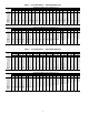
Table 78 — 5K Thermistor Temperature vs. Resistance (SCT Sensors) (English) TEMP (F) –25 –24 –23 –22 –21 –20 –19 –18 –17 –16 –15 –14 –13 –12 –11 –10 –9 –8 –7 –6 –5 –4 –3 –2 –1 0 1 2 3 4 5 6 7 8 9 10 11 12 13 14 15 16 17 18 19 20 21 22 23 24 25 26 27 28 29 30 31 32 33 34 35 36 37 38 39 40 41 42 43 44 45 46 47 48 49 50 51 52 53 54 55 56 57 58 VOLTAGE DROP (V) 3.699 3.689 3.679 3.668 3.658 3.647 3.636 3.624 3.613 3.601 3.588 3.576 3.563 3.550 3.536 3.523 3.509 3.494 3.480 3.465 3.450 3.434 3.418 3.402 3.
Table 79 — 5K Thermistor Temperature vs. Resistance (SCT Sensors) (SI) TEMP (C) –32 –31 –30 –29 –28 –27 –26 –25 –24 –23 –22 –21 –20 –19 –18 –17 –16 –15 –14 –13 –12 –11 –10 –9 –8 –7 –6 –5 –4 –3 –2 –1 0 1 2 3 4 5 6 7 8 9 10 11 12 13 14 VOLTAGE DROP (V) 3.705 3.687 3.668 3.649 3.629 3.608 3.586 3.563 3.539 3.514 3.489 3.462 3.434 3.406 3.376 3.345 3.313 3.281 3.247 3.212 3.177 3.140 3.103 3.065 3.025 2.985 2.945 2.903 2.860 2.817 2.774 2.730 2.685 2.639 2.593 2.547 2.500 2.454 2.407 2.360 2.312 2.265 2.217 2.
Table 80 — 10K Thermistor vs. Resistance (T55, T56, OAT, RAT, EDT, LAT Sensors) (English) TEMP (F) –25 –24 –23 –22 –21 –20 –19 –18 –17 –16 –15 –14 –13 –12 –11 –10 –9 –8 –7 –6 –5 –4 –3 –2 –1 0 1 2 3 4 5 6 7 8 9 10 11 12 13 14 15 16 17 18 19 20 21 22 23 24 25 26 27 28 29 30 31 32 33 34 35 36 37 38 39 40 41 42 43 44 45 46 47 48 49 50 51 52 53 54 55 56 57 58 59 60 VOLTAGE DROP (V) 4.758 4.750 4.741 4.733 4.724 4.715 4.705 4.696 4.686 4.676 4.665 4.655 4.644 4.633 4.621 4.609 4.597 4.585 4.572 4.560 4.546 4.
Table 81 — 10K Thermistor vs. Resistance (T55, T56, OAT, RAT, EDT, LAT Sensors) (SI) TEMP (C) –32 –31 –30 –29 –28 –27 –26 –25 –24 –23 –22 –21 –20 –19 –18 –17 –16 –15 –14 –13 –12 –11 –10 –9 –8 –7 –6 –5 –4 –3 –2 –1 0 1 2 3 4 5 6 7 8 9 10 11 12 13 14 VOLTAGE DROP (V) 4.762 4.748 4.733 4.716 4.700 4.682 4.663 4.644 4.624 4.602 4.580 4.557 4.533 4.508 4.482 4.455 4.426 4.397 4.367 4.335 4.303 4.269 4.235 4.199 4.162 4.124 4.085 4.044 4.003 3.961 3.917 3.873 3.828 3.781 3.734 3.686 3.637 3.587 3,537 3.485 3.
Run Status→VIEW→H.MAX — Displays the maximum number of heat stages available for this model. ECONOMIZER RUN STATUS — The Economizer Run Status display table provides information about the economizer and can be used to troubleshoot economizer problems. See Table 84. The current position, commanded position, and whether the economizer is active can be displayed. All the disabling conditions for the economizer and outside air information is also displayed.
Cap Threshold Adding (Z.PLU) — This parameter is used in the calculation of SMZ and is calculated as follows: Z.PLU = Configuration→COOL→Z.GN * (10 + (4* (–ADD.R))) * 0.6 High Temp Cap Override (H.TMP) — If stages of mechanical cooling are on and the error is greater than twice Y.PLU, and the rate of change of error is greater than 0.5° F, then a stage of mechanical cooling will be added every 30 seconds. This override is intended to react to situations where the load rapidly increases.
Table 85 — Cooling Information Display Table ITEM COOL C.CAP CUR.S REQ.S MAX.S DEM.L SUMZ SMZ ADD.R SUB.R R.PCT Y.MIN Y.PLU Z.MIN Z.PLU H.TMP L.TMP PULL SLOW EXPANSION COOLING INFORMATION Current Running Capacity Current Cool Stage Requested Cool Stage Maximum Cool Stages Active Demand Limit COOL CAP.
Table 90 — Time Guard Display Table ITEM TMGD TG.A1 TG.A2 TG.B1 TG.B2 TG.H1 TG.H2 TG.H3 TG.H4 TG.H5 TG.
Table 92 — Alert and Alarm Codes ALARM OR ALERT NUMBER A051 DESCRIPTION A051 Circuit A, Compressor 1 Current Detected After Shutdown P051 Compressor A1 Safety Trip T051 A052 Circuit A, Compressor 1 Failure Circuit A, Compressor 2 Current Detected After Shutdown P052 Circuit A, Compressor 2 Failure T052 A055 Circuit A, Compressor 2 Failure Circuit B, Compressor 1 Current Detected After Shutdown P055 Circuit B, Compressor 1 Failure T055 A056 Circuit B, Compressor 1 Failure Circuit B, Compressor 2
Table 92 — Alert and Alarm Codes (cont) ALARM OR ALERT NUMBER ACTION TAKEN BY CONTROL RESET METHOD PROBABLE CAUSE Automatic Outdoor dampers stuck, no load Space Temperature Above Limit Stop cooling, but continue to heat Stop heating, but continue to cool Automatic High load, dampers open T302 Supply Temperature Below Limit Continue to run unit Automatic T303 Supply Temperature Above Limit Continue to run unit Automatic T304 Return Temperature Below Limit Continue to run unit Automatic
5. Return to Normal mode and observe compressor operation to verify that compressor current sensor is working and condenser fans are energized after compressor starts. Alert Codes 64, and 65 (Condensing Temp. Failure) — Alert codes 64, and 65 are for circuits A and B, respectively. These alerts occur when the saturated condensing temperatures (Temperatures→REF.T→SCT.A and SCT.B) are outside the range –40 to 240 F (–40 to 116 C).
coupled with dirty outdoor coil, plugged filter drier, or a faulty high-pressure switch. The alert will clear automatically or when the OAT drops 5° F from the time of the alert. Alarm Code 150 (Unit in Emergency Stop) — If the fire safety input condition occurs to indicate a fire or smoke condition, then Alarm code 150 will occur and the unit will be immediately stopped. Through separate inputs the unit can be put into purge, evacuation, and pressurization. This requires a manual reset.
(Configuration→ALLM→SA.L.O) for 5 minutes or the Low Supply air temperature alert limit unoccupied mode (Configuration→ALLM→SA.L.U) for 10 minutes, then an alert will be broadcast. Alert Code 303 (Supply Temperature Above Limit) — If the supply temperature is above the configurable SAT HI Alert Limit Occ (Configuration→ALLM→SAH.O) for 5 minutes or the SAT HI Alert Limit/Unocc (Configuration→ALLM →SA.H.U) for 10 minutes, then an alert will be broadcast. The alert will automatically reset.
Alarm and Alert Codes 409 (Supply Fan Commanded On, Sensed Off Failure and Supply Fan Commanded Off, Sensed On Failure) —Both the alert and the alarm refer to the same failure. The only difference between the alarm and alert is that in the case where the supply fan status configuration to shut down the unit is set to YES (Configuration→UNIT→ SFS.S), the alarm will be generated AND the unit will be shut down. It is possible to configure Configuration→UNIT→SFS.M to either a switch or to monitor a 0.2-in.
Factory-Installed Components Alert Code 423 (Y and W Simultaneously) — This alert occurs in Thermostat Mode when Y1 or Y2 is energized simultaneously with W1 or W2. Verify thermostat and thermostat wiring. The software will enter either the cooling or heating mode depending upon which input turned on first. This alert resets automatically when Y1 and Y2 are not on simultaneously with W1 and W2.
Fig.
TO NEXT PAGE Fig.
LEN PORT FOR USE WITH NAVIGATOR Fig.
Fig.
TO NEXT PAGE Fig.
FROM PREVIOUS PAGE Fig.
Fig.
TO NEXT PAGE Fig.
FROM PREVIOUS PAGE Fig.
Fig.
Fig.
Fig.
LEGEND AND NOTES FOR FIG.
RED LED - STATUS GREEN LEDLEN (LOCAL EQUIPMENT NETWORK) YELLOW LED CCN (CARRIER COMFORT NETWORK) INSTANCE JUMPER (SET TO 1) CEPL130346-01 HK 50AA029 CE BO 430346 J1 J4 STATUS J2 J10 LEN J3 J5 J6 J7 J9 J8 Fig.
Fig.
Table 95 — Valve Control Board (ECB2) Inputs and Outputs POINT NAME INPUTS POINT DESCRIPTION I/O POINT NAME PLUG AND PIN REFERENCE SIGNAL PIN(S) PORT STATE DI1 DI2 AN1 AN2 J4, 1-2 J4, 3-4 J5, 1-3 J5, 4-6 2 4 1=24VDC, 2=0-20mA in, 3=GND 4=24VDC, 5=0-20mA in, 6=GND 24VAC = 1, 0VAC = 0 24VAC = 1, 0VAC = 0 0-20mA 0-20mA AO1 PP/MP RLY1 RLY 2 RLY 3 RLY 6 J9, 1-2 J7, 1-3 J8, 1-3 J8, 4-6 J8, 7-9 J8, 16-18 1=0-20mA, 2=GND 1=PP/MP Data, 2=24VAC, 3=GND 1 = 2 = RLY1A, 3 = RLY1B 4 =5 = RLY2A, 6 = RLY2B 7 = 8
Table 96 — Staged Gas Control Board (SCB) Inputs and Outputs POINT NAME INPUTS POINT DESCRIPTION I/O POINT NAME PLUG AND PIN REFERENCE SIGNAL PIN(S) PORT STATE AN1 AN2 AN3 AN4 AN5 AN6 AN7 AN8 AN9 AN10 J5, 1-3 J5, 4-6 J5, 7-9 J5, 10-12 J5, 13-15 J6, 1-3 J6, 4-6 J6, 7-9 J7, 1-2 J7, 3-4 1=5v, 2=Vin, 3=GND (thermistor 1-2) 4=5v, 5=Vin, 6=GND (thermistor 4-5) 7=5v, 8=Vin, 9=GND (thermistor 7-8) 10=5v, 11=Vin, 12=GND (thermistor 10-11) 13=5v, 14=Vin, 15=GND (thermistor 13-14) 1=5v, 2=Vin, 3=GND (thermisto
Table 97 — Controls Expansion Board (CEM) Inputs POINT NAME INPUTS SFS DMD_SW1 DMD_SW2 PRES EVAC PURG IAQIN DMDLMTMA EDTRESMA OAQ SPRESET POINT DESCRIPTION I/O POINT NAME PLUG AND PIN REFERENCE SIGNAL PIN(S) PORT STATE DI 1 DI 2 DI 3 DI 4 DI 5 DI 6 DI 7 AN7 AN8 AN9 AN10 AN10 J7, 1-2 J7, 3-4 J7, 5-6 J7, 7-8 J7, 9-10 J7, 11-12 J7, 13-14 J6, 1-3 J6, 4-6 J6, 7-9 J6, 10-12 J6, 10-12 2 4 6 8 10 12 14 2 (1 = loop power) 5 (4 = loop power) 8 (7 = loop power) 11 (10 = loop power) 11 (10 = loop power) 0 = 24
FILTER STATUS SWITCH — The units can be equipped with an optional filter status switch. The switch measures the pressure drop across the filters and closes when an adjustable pressure set point is exceeded. The sensor is located in the return air section behind the filter access door. RETURN AIR CO2 SENSOR — The unit can also be equipped with a return air IAQ CO2 sensor that is used for the demand control ventilation.
FIELD CONNECTION TERMINAL STRIPS — Field connection terminal strips are located in the main control box. See Fig. 28 and Table 100. for normal 2-stage control, it is recommended that the multistage control be used. The room thermostat is connected to TB4. SPACE SENSOR — The ComfortLink control supports the use of space temperature sensors. The T55 and T56 sensors and CCN communicating T58 room sensor can be used. The T55 and T56 sensors are connected to TB5 terminal 3, 4, and 5.
Table 100 — Field Connection Terminal Strips TERMINAL TERMINAL DESCRIPTION BOARD NO.
drain wire and is field supplied and installed. See the Installation instructions for wiring information. The system elements are connected to the communication bus in a daisy chain arrangement. The positive pin of each system element communication connector must be wired to the positive pins of the system elements on either side of it. This is also required for the negative and signal ground pins of each system element. Wiring connections for CCN should be made at TB3. See Fig. 31.
CCN BUS ROOFTOP UNIT ROOFTOP UNIT CL CL COMPUTER WITH COMPUTER WITH ComfortVIEW™ ComfortView™ SOFTWARE SOFTWARE CCN WEB OR NETWORK OPTIONS ROOFTOP UNIT ROOFTOP UNIT CL CL HEATING/COOLING UNITS REMOTE CCN SITE TELINK BRIDGE (RECOMMENDED) TO ADDITIONAL TERMINALS CL CID ROOFTOP UNIT CID COMFORT ID AIR TERMINAL CID COMFORT ID AIR TERMINAL NON CARRIER HVAC EQUIPMENT COMFORT CONTROLLER CCN CID CL HVAC — — — — AIR DISTRIBUTION-DIGITAL AIR VOLUME CONTROL (DAV) LEGEND Carrier Comfort Network C
SERVICE Remove Surface Loaded Fibers — Surface loaded fibers or dirt should be removed with a vacuum cleaner. If a vacuum cleaner is not available, a soft non-metallic bristle brush may be used. In either case, the tool should be applied in the direction of the fins. Coil surfaces can be easily damaged (fin edges can be easily bent over and damage to the coating of a protected coil) if the tool is applied across the fins.
8. Interior and exterior finned areas must be thoroughly cleaned. 9. Finned surfaces should remain wet with cleaning solution for 10 minutes. 10. Ensure surfaces are not allowed to dry before rinsing. Reapplying cleaner as needed to ensure 10-minute saturation is achieved. 11. Thoroughly rinse all surfaces with low velocity clean water using downward rinsing motion of water spray nozzle. Protect fins from damage from the spray nozzle. CONDENSATE DRAIN — Check and clean each year at start of cooling season.
NOTES: 1. Torque set screws on blower wheel to 70 in. lb ± 2 in. lb. 2. Torque set screw on propeller fan to 15 in. lb ± 2 in. lb. 3. Dimensions are in inches. Fig. 34 — Typical Gas Heating Section Evaporator Fan Coupling Assembly — If the coupling has been removed for other blower assembly component repair or replacement, it is critical that the coupling be reassembled and aligned correctly to prevent premature failures. REASSEMBLING THE COUPLING INTO THE UNIT (Fig. 37) 1.
8. Pivot the front of the motor plate upward enough to allow access to the motor mounting hex bolts and secure in place by inserting a prop. 9. Remove the nuts from the motor mounting hex bolts and remove motor. 10. Replace the locktooth washer under the motor base with a new washer. Be sure that the washer contacts the motor base surface. 11. Reverse above steps to install new motor. 13. Reinstall drive belts. (Refer to Belt Tension Adjustment section below.) 14. Visually inspect the assembly.
Thermostatic Expansion Valve (TXV) — Each circuit 7. Remove sensor wire and ignitor cable from IGC board. 8. Remove 2 screws securing manifold bracket to basepan. 9. Remove 4 screws that hold the burner support plate flange to the vestibule plate. 10. Lift burner assembly out of unit. 11. Reverse procedure to re-install burners. has a TXV. The TXV is nonadjustable and is factory set to maintain 10 to 13° F superheat leaving the evaporator coil.
APPENDIX A — LOCAL DISPLAY TABLES MODE — RUN STATUS ITEM VIEW →HVAC →OCC →MAT →EDT →LAT →EC.C.P →ECN.P →CL.C.P →C.CAP →HT.C.P →HT.ST →H.MAX ECON →ECN.P →ECN.C →ACTV →DISA →DISA→UNAV →DISA→R.EC.D →DISA→DBC →DISA→DEW →DISA→DDBC →DISA→OAEC →DISA→DEC →DISA→EDT →DISA→OAT →DISA→FORC →DISA→SFON →DISA→CLOF →DISA→OAQL →DISA→HELD →O.AIR →O.AIR→OAT →O.AIR→OA.RH →O.AIR→OA.E →O.AIR→OA.D.T COOL →C.CAP →CUR.S →MAX.S →DEM.L →SUMZ →SUMZ→SMZ →SUMZ→ADD.R →SUMZ→SUB.R →SUMZ→R.PCT →SUMZ→Y.MIN →SUMZ→Y.PLU →SUMZ→Z.MIN →SUMZ→Z.
APPENDIX A — LOCAL DISPLAY TABLES (cont) MODE — RUN STATUS (cont) ITEM EXPANSION TMGD →TG.A1 →TG.A2 →TG.B1 →TG.B2 →TG.H1 →TG.H2 →TG.H3 →TG.H4 →TG.H5 →TG.
APPENDIX A — LOCAL DISPLAY TABLES (cont) MODE — PRESSURES ITEM AIR.P →SP →BP REF.P →DP.A →SP.A →DP.B →SP.B EXPANSION AIR PRESSURES Static Pressure Building Pressure REFRIGERANT PRESSURES Cir A Discharge Pressure Cir A Suction Pressure Cir B Discharge Pressure Cir B Suction Pressure RANGE UNITS CCN POINT "H2O "H2O SP BP PSIG PSIG PSIG PSIG DP_A SP_A DP_B SP_B WRITE STATUS MODE — SET POINTS ITEM OHSP OCSP UHSP UCSP GAP V.C.ON V.C.OF SASP SA.HI SA.LO SA.HT T.PRG T.CL T.V.OC T.V.
APPENDIX A — LOCAL DISPLAY TABLES (cont) MODE — INPUTS (cont) ITEM 4-20 →IAQ.M →OAQ.M →SP.R.M →DML.M →EDR.M →ORH.M →RRH.M →BP.M →BP.M.T →SP.M →SP.M.T EXPANSION 4-20 MILLIAMP INPUTS IAQ Milliamps OAQ Milliamps SP Reset milliamps 4-20 ma Demand Signal EDT Reset Milliamps OARH Milliamps RARH Milliamps BP Milliamps Bldg. Pressure Trim (ma) SP Milliamps Static Press.
APPENDIX A — LOCAL DISPLAY TABLES (cont) MODE — CONFIGURATION (cont) ITEM COOL →Z.GN →MC.LO →C.FOD →MLV →M.M. →HPSP →A1.EN →A2.EN →B1.EN →B2.EN →CS.A1 →CS.A2 →CS.B1 →CS.B2 →REV.R EDT.R →RS.CF →RTIO →LIMT →RES.S HEAT →HT.CF →HT.SP →OC.EN →LAT.M →G.FOD →E.FOD →SG.CF →SG.CF→HT.ST →SG.CF→CAP.M →SG.CF→M.R.DB →SG.CF→S.G.DB →SG.CF→RISE →SG.CF→LAT.L →SG.CF→LIM.M →SG.CF→SW.H.T →SG.CF→SW.L.T →SG.CF→HT.P →SG.CF→HT.D →SG.CF→HT.TM SP →SP.CF →SP.FN →SP.S →SP.LO →SP.HI →SP.SP →SP.MN →SP.MX →SP.FS →S.PID →S.PID->SP.TM →S.
APPENDIX A — LOCAL DISPLAY TABLES (cont) MODE — CONFIGURATION (cont) ITEM BP →BP.CF →BP.MT →BP.S →BP.R →BP.SP →BP.P1 →BP.P2 →B.CFG →B.CFG→BP.SL →B.CFG→BP.TM →B.CFG→BP.ZG →B.CFG→BP.HP →B.CFG→BP.LP D.LV.T →L.H.ON →H.H.ON →L.H.OF →L.C.ON →H.C.ON →L.C.OF →C.T.LV →H.T.LV →C.T.TM →H.T.TM DMD.L →DM.L.S →D.L.20 →SH.NM →SH.DL →SH.TM →D.L.S1 →D.L.S2 IAQ →DCV.C →DCV.C→EC.MN →DCV.C→IAQ.M →AQ.CF →AQ.CF→IQ.A.C →AQ.CF→IQ.A.F →AQ.CF→IQ.I.C →AQ.CF→IQ.I.F →AQ.CF→OQ.A.C →AQ.SP →AQ.SP→IQ.O.P →AQ.SP→DAQ.L →AQ.SP→DAQ.H →AQ.SP→D.
APPENDIX A — LOCAL DISPLAY TABLES (cont) MODE — CONFIGURATION (cont) ITEM ALLM →SP.L.O →SP.H.O →SP.L.U →SP.H.U →SA.L.O →SA.H.O →SA.L.U →SA.H.U →RA.L.O →RA.H.O →RA.L.U →RA.H.U →R.RH.L →R.RH.H →SP.L →SP.H →BP.L →BP.H →IAQ.H TRIM →SAT.T →RAT.T →OAT.T →SPT.T →CTA.T →CTB.T →SP.A.T →SP.B.T →DP.A.T →DP.B.T SW.LG →FTS.L →IGC.L →RMI.L →ECS.L →SFS.L →DL1.L →DL2.L →IAQ.L →FSD.L →PRS.L →EVC.L →PRG.L DISP →TEST →METR →LANG →PAS.E →PASS EXPANSION ALERT LIMIT CONFIG.
APPENDIX A — LOCAL DISPLAY TABLES (cont) MODE — TIME CLOCK (cont) ITEM Repeated for holidays 2-30…….. DAY.S DS.ST DS.ST→ST.MN DS.ST→ST.WK DS.ST→ST.DY DS.ST→MIN.A DS.SP DS.SP→SP.MN DS.SP→SP.WK DS.SP→SP.DY DS.SP→MIN.S EXPANSION RANGE DAYLIGHT SAVINGS TIME DAYLIGHT SAVINGS START Month Week Day Minutes to Add DAYLIGHTS SAVINGS STOP Month Week Day Minutes to Subtract UNITS CCN POINT DEFAULT PAGE NO.
APPENDIX B — CCN TABLES (cont) STATUS DISPLAY TABLES (cont) TABLE COOL_B DISPLAY NAME RANGE Compressor B1 Relay Compressor B1 Feedback Compressor B1 Timeguard Compressor B2 Relay Compressor B2 Feedback Compressor B2 Timeguard Cir B Discharge Pressure Cir B Suction Pressure Cir B Sat.Condensing Tmp Cir B Sat.Suction Temp.
APPENDIX B — CCN TABLES (cont) STATUS DISPLAY TABLES (cont) TABLE HEATING DISPLAY NAME HVAC Mode…………..: Control Mode………..: Heat Control Type……: Heating Mode………..
APPENDIX B — CCN TABLES (cont) STATUS DISPLAY TABLES (cont) TABLE UINPUTS DISPLAY NAME Filter Status Input Fan request from IGC Fire Shutdown Switch Thermostat G Input Thermostat W2 Input Thermostat W1 Input Thermostat Y2 Input Thermostat Y1 Input Economizer Control Input Remote Economizer Enable Econo Position Override Remote Input State Supply Fan Status Switch Demand Limit Switch 1 Demand Limit Switch 2 Pressurization Input Evacuation Input Smoke Purge Input IAQ - Discrete Input RANGE UNITS Dirty/Cle
APPENDIX B — CCN TABLES (cont) CONFIG TABLES (cont) TABLE BRODEFS NAME RANGE UNITS POINT NAME DEFAULT CCN Time/Date Broadcast CCN OAT Broadcast CCN OARH Broadcast CCN OAQ Broadcast Global Schedule Broadcst Daylight Savings Start: Month Week Day Minutes to Add Daylight Savings Stop: Month Week Day Minutes to Subtract Off/On Off/On Off/On Off/On Off/On CCNBC OATBC OARHBC OAQBC GSBC Off Off Off Off Off 1 - 12 1-5 1-7 0 - 90 STARTM STARTW STARTD MINADD 4 1 7 60 1 - 12 1-5 1-7 0 - 90 STOPM STOPW ST
APPENDIX B — CCN TABLES (cont) SERVICE-CONFIG TABLES TABLE ALLM NAME RANGE SPT lo alert limit/occ SPT hi alert limit/occ SPT lo alert limit/unocc SPT hi alert limit/unocc EDT lo alert limit/occ EDT hi alert limit/occ EDT lo alert limit/unocc EDT hi alert limit/unocc RAT lo alert limit/occ RAT hi alert limit/occ RAT lo alert limit/unocc RAT hi alert limit/unocc RARH low alert limit RARH high alert limit SP low alert limit SP high alert limit BP lo alert limit BP high alert limit IAQ high alert limit –10-
APPENDIX B — CCN TABLES (cont) SERVICE-CONFIG TABLES (cont) TABLE ECON NAME RANGE Economizer Installed ? Economizer Min.Position Economizer Max.Position Economzr trim for sumZ ? Econ ChangeOver Select OA Enthalpy ChgOvr Selct Outdr.Enth Compare Value High OAT Lockout Temp OA Dewpoint Temp Limit Outside Air RH Sensor Economizer Control Type Economizer Switch Config Economizer Prop.Gain Economizer Range Adjust Economizer Speed Adjust Economizer Deadband Unoc Econ Free Cool Cfg Unoc Econ Free Cool Time Un.
APPENDIX B — CCN TABLES (cont) SERVICE-CONFIG TABLES (cont) TABLE TRIM NAME RANGE Air Temp Lvg SF Trim RAT Trim OAT Trim SPT Trim Cir A Sat.Cond.Temp Trim Cir B Sat.Cond.Temp Trim Suct.Press.Circ.A Trim Suct.Press.Circ.B Trim Dis.Press.Circ.A Trim Dis.Press.Circ.B Trim Static Press. Trim (ma) Bldg.
APPENDIX B — CCN TABLES (cont) MAINTENANCE DISPLAY TABLES TABLE ALARMS01 DISPLAY NAME RANGE UNITS POINT NAME Active Alarm ------------------------ ascii ascii ALARM_01 Active Alarm ------------------------ ascii ascii ALARM_02 Active Alarm ------------------------ ascii ascii ALARM_03 Active Alarm ------------------------ ascii ascii ALARM_04 Compressor A1 Relay Compressor A1 Feedback Curr.Sens.Brd.
APPENDIX B — CCN TABLES (cont) MAINTENANCE DISPLAY TABLES (cont) TABLE ECON_MIN DISPLAY NAME RANGE Econo Damper Command Pos Econo Damper Current Pos Econo Current Min. Pos. Diff.Air Quality in PPM Econo Position Override IAQ Min.Pos.Override Econ Remote 10K Pot Val. IAQ - PPM Return CO2 OAQ - PPM Return CO2 IAQ - Discrete Input IAQ Demand Vent Min.Pos. Economizer Min.Position IAQ Analog Sensor Config IAQ 4-20 ma Fan Config IAQ Discrete Input Confg IAQ Disc.In. Fan Config IAQ Econo Override Pos. Diff.
APPENDIX B — CCN TABLES (cont) MAINTENANCE DISPLAY TABLES (cont) TABLE ENTHALPY DISPLAY NAME RANGE Outdoor Air Enthalpy Outside Air Temperature Outside Air Rel.Humidity Outside Air RH Sensor OA Dewpoint Temp Limit OutsideAir DewPoint Temp OutsideAir Humidty Ratio OA H2O Vapor Sat.Pressur OA H2O Partial.Press.Vap Return Air Enthalpy Return Air Temperature Controlling Return Temp Return Air Rel.Humidity Return Air Temp Sensor Return Air RH Sensor Altitude……..
APPENDIX B — CCN TABLES (cont) MAINTENANCE DISPLAY TABLES (cont) TABLE PRESBLDG DISPLAY NAME RANGE UNITS Building Pressure Econo Damper Current Pos Power Exhaust Stage A Power Exhaust Stage B Power Exhaust Stage C BP Load Factor BP Rise Per Stage BP PID/Integral Term BP PID Threshold BP Deadband Building Pressure Error Rate of Chng of BPERROR High BP Override Low BP Override "H2O % Static Pressure Supply Fan VFD Speed Static Pressure Setpoint Static Pressure Reset "H2O % "H2O POINT NAME WRITE STATU
APPENDIX B — CCN TABLES (cont) MAINTENANCE DISPLAY TABLES (cont) TABLE TESTCOOL DISPLAY NAME RANGE Compressor A1 Relay Compressor A2 Relay Min.
APPENDIX C — VFD INFORMATION On variable air volume units with optional VFD, the supply fan speed is controlled by a 3-phase VFD. The VFD is located in the supply fan section behind a removable panel. The VFD speed is controlled directly by the ComfortLink™ controls through a 4 to 20 mA signal based on a supply duct pressure sensor.
Table B — VFD Configurations PARAMETER GROUP Start-Up Data Start/Stop/Dir Analog Inputs Relay Outputs System Controls OVER RIDE Accel/Decel MOTOR PARAMETER TITLE LANGUAGE APPLIC MACRO MOTOR CTRL MODE MOTOR NOM VOLT MOTOR NOM CURR MOTOR NOM FREQ MOTOR NOM SPEED EXT1 COMMANDS DIRECTION MINIMUM AI1 MAXIMUM AI1 RELAY OUTPUT 1 RELAY OUTPUT 2 RELAY OUTPUT 3 RUN ENABLE START ENABLE 1 OVERRIDE SEL OVERRIDE FREQ OVERRIDE SPEED OVER PASS CODE OVERRIDE STOP FUNCTION ACCELER TIME 1 DECELER TIME 1 SWITCHING FREQ
STANDARD DISPLAY MODE — Use the standard display mode to read information on the drive status and operate the drive. To reach the standard display mode, press EXIT until the LCD display shows status information as described below. See Fig. C. The top line of the LCD display shows the basic status information of the drive. The HAND icon indicates that the drive control is local from the control panel. The AUTO icon indicates that the drive is in remote control mode, such as the basic I/O (X1) or field bus.
Upload All Parameters — To upload and store parameters in the control panel from the VFD, perform the following procedure: 1. Select MENU (SOFT KEY 2). The Main menu will be displayed. 2. Use the UP or DOWN keys to highlight PAR BACKUP on the display screen and press ENTER (SOFT KEY 2). 3. Use the UP or DOWN keys to highlight UPLOAD TO PANEL and press SEL (SOFT KEY 2). 4. The text “Copying Parameters” will be displayed with a progress indicator. To stop the process, select ABORT (SOFT KEY 1). 5.
Third Party Controls — For conversion to third party CLOCK SET MODE — The clock set mode is used for setting the date and time for the internal clock of the VFD. In order to use the timer functions of the VFD control, the internal clock must be set. The date is used to determine weekdays and is visible in the fault logs. To set the clock, perform the following procedure: 1. Select MENU (SOFT KEY 2). The Main menu will be displayed. 2.
Table C — Fault Codes FAULT CODE FAULT NAME IN PANEL 1 OVERCURRENT 2 DC OVERVOLT 3 DEV OVERTEMP 4 5 SHORT CIRC OVERLOAD 6 DC UNDERVOLT 7 AI1 LOSS 8 AI2 LOSS 9 MOT OVERTEMP 10 PANEL LOSS 11 ID RUN FAIL 12 MOTOR STALL 13 14 15 RESERVED EXT FAULT 1 EXT FAULT 2 16 EARTH FAULT 17 UNDERLOAD 18 19 20 21 22 23 THERM FAIL OPEX LINK OPEX PWR CURR MEAS SUPPLY PHASE RESERVED 24 OVERSPEED 25 26 27 RESERVED DRIVE ID CONFIG FILE 28 SERIAL 1 ERR 29 30 31 32 33 EFB CON FILE FORCE TRIP
speed at the time of the fault. To clear the fault history (all of Group 04, Fault History parameters), follow these steps: 1. In the control panel, Parameters mode, select parameter 0401. 2. Press EDIT. 3. Press the UP and DOWN buttons simultaneously. 4. Press SAVE. CORRECTING ALARMS — To correct alarms, first determine if the Alarm requires any corrective action (action is not always required). Use Table D below to find and address the root cause of the problem.
If diagnostics troubleshooting has determined that the drive is defective during the warranty period, contact ABB Automation Inc., at 1-800-435-7365, option 4, option 3. A qualified technician will review the problem with the caller and make a determination regarding how to proceed. This may involve dispatching a designated service station (DSS) representative from an authorized station, dispatching a replacement unit, or advising return for repair.
6. Install the fan in reverse order, noting the following: the fan airflow is up (refer to arrow on fan); the fan wire harness is toward the front; the notched housing barb is located in the right-rear corner; and the fan cable connects just forward of the fan at the top of the drive. To replace the internal enclosure fan for frame sizes R5 or R6, perform the following: 1. Remove power from drive. 2. Remove the front cover. 3. Lift the fan out and disconnect the cable. 4. Install the fan in reverse order.
Else If: A compressor is diagnosed as being “Stuck On” — { HVAC mode: ("Comp. Stuck On ") Else The control is free to select the normal heating/ cooling HVAC modes: — { — — — — — HVAC mode: ("Off ") The unit is off and no operating modes are active. HVAC mode: ("Tempering Vent ") The economizer is at minimum vent position but the supply air temperature has dropped below the tempering vent set point. Gas heat is used to temper the ventilation air.
INDEX Accessory control components 105 Accessory installation 7 Accessory Navigator™ display 4, 107 Airflow control during fire-smoke modes 56 Alarm output 24 Alarms and alerts 78 Alert limit configuration 60 Auto view of run status 75 Basic control usage 3-6 Building pressure configuration 54 Building pressure control 54 Carrier Comfort Network (CCN) 59 CCN tables and display 5 CCN tables 121-133 Cleaning 109 ComfortLink™ control 3 Complete unit stoppage 66 Compressor run hours display table 76 Compressor
CONTROLS SET POINT AND CONFIGURATION LOG MODEL NUMBER: Software Version SERIAL NUMBER: MBB CESR131292-- DATE: RCB CESR131249-- TECHNICIAN: ECB CESR131249-- NAVI CESR131227-- SCB CESR131226-- CEM CESR131174-- MARQ CESR131171-- ITEM UNIT →C.TYP →CV.FN →RM.CF →CEM →TCS.C →TCS.H →SFS.S →SFS.M →VAV.S →SIZE →DP.XR →MAT.S →MAT.R →ALTI →SENS →SENS→SPT.S →SENS→SP.O.S →SENS→SP.O.R →SENS→RRH.S →SENS→FLT.S →SENS→SP.RS COOL →Z.GN →MC.LO →C.FOD →MLV →M.M. →HPSP →A1.EN →A2.EN →B1.EN →B2.EN →CS.A1 →CS.
EXPANSION HEATING CONFIGURATION Heating Control Type Heating Supply Air Setpt Occupied Heating Enabled MBB Sensor Heat Relocate Fan-Off Delay, Gas Heat Fan-Off Delay, Elec Heat STAGED GAS CONFIGS Staged Gas Heat Type Max Cap Change per Cycle S.Gas DB min.dF/PID Rate St.Gas Temp. Dead Band Heat Rise dF/sec Clamp LAT Limit Config Limit Switch Monitoring? Limit Switch High Temp Limit Switch Low Temp Heat Control Prop. Gain Heat Control Derv. Gain Heat PID Rate Config SUPPLY STATIC PRESS.CFG.
ITEM BP →BP.CF →BP.MT →BP.S →BP.R →BP.SP →BP.P1 →BP.P2 →B.CFG →B.CFG→BP.SL →B.CFG→BP.TM →B.CFG→BP.ZG →B.CFG→BP.HP →B.CFG→BP.LP D.LV.T →L.H.ON →H.H.ON →L.H.OF →L.C.ON →H.C.ON →L.C.OF →C.T.LV →H.T.LV →C.T.TM →H.T.TM DMD.L →DM.L.S →D.L.20 →SH.NM →SH.DL →SH.TM →D.L.S1 →D.L.S2 IAQ →DCV.C →DCV.C→EC.MN →DCV.C→IAQ.M →AQ.CF →AQ.CF→IQ.A.C →AQ.CF→IQ.A.F →AQ.CF→IQ.I.C →AQ.CF→IQ.I.F →AQ.CF→OQ.A.C →AQ.SP →AQ.SP→IQ.O.P →AQ.SP→DAQ.L →AQ.SP→DAQ.H →AQ.SP→D.F.OF →AQ.SP→D.F.ON →AQ.SP→IAQ.R →AQ.SP→OAQ.L →AQ.SP→OAQ.U →AQ.S.
EXPANSION CCN CONFIGURATION CCN Address CCN Bus Number CCN Baud Rate CCN BROADCST DEFINITIONS CCN Time/Date Broadcast CCN OAT Broadcast CCN OARH Broadcast CCN OAQ Broadcast Global Schedule Broadcst CCN Broadcast Ack'er CCN SCHEDULES-OVERRIDES Schedule Number Accept Global Holidays? Override Time Limit Timed Override Hours SPT Override Enabled ? T58 Override Enabled ? Global Sched. Override ? ALERT LIMIT CONFIG.
UNIT START-UP CHECKLIST MODEL NO.: _________________________________ SERIAL NO.
Manufacturer reserves the right to discontinue, or change at any time, specifications or designs without notice and without incurring obligations. PC 111 Catalog No. 534-80215 Printed in U.S.A.