
Specifications

2
CONTENTS (cont)
Page
Indoor Air Quality Control ........................56
•OPERATION
• SETTING UP THE SYSTEM
• PRE-OCCUPANCY PURGE
Temperature Compensated Start ..................59
• SETTING UP THE SYSTEM
• TEMPERATURE COMPENSATED START LOGIC
Carrier Comfort Network (CCN) ...................59
Alert Limit Configuration .........................60
Sensor Trim Configuration........................61
Discrete Switch Logic Configuration ..............62
Display Configuration ............................62
Remote Control Switch Input .....................63
Hot Gas Bypass ..................................63
Space Temperature Offset ........................64
TIME CLOCK CONFIGURATION ................ 64,65
TROUBLESHOOTING ..........................66-85
Complete Unit Stoppage..........................66
Single Circuit Stoppage ..........................66
Service Analysis .................................66
Restart Procedure................................66
Thermistor Troubleshooting ......................66
Transducer Troubleshooting ......................66
Forcing Inputs and Outputs.......................75
Run Status Menu .................................75
• AUTO VIEW OF RUN STATUS
• ECONOMIZER RUN STATUS
• COOLING INFORMATION
• MODE TRIP HELPER
• CCN/LINKAGE DISPLAY TABLE
• COMPRESSOR RUN HOURS DISPLAY TABLE
• COMPRESSOR STARTS DISPLAY TABLE
• TIME GUARD DISPLAY TABLE
• SOFTWARE VERSION NUMBERS DISPLAY TABLE
Alarms and Alerts ................................78
MAJOR SYSTEM COMPONENTS ..............85-108
General ..........................................85
Factory-Installed Components ....................85
Accessory Control Components .................105
SERVICE ....................................109-113
Service Access..................................109
Cleaning ........................................109
Lubrication .....................................110
Evaporator Fan Performance Adjustment.........110
Evaporator Fan Coupling Assembly ..............111
Evaporator Fan Service and Replacement ........112
Belt Tension Adjustment.........................112
Evaporator-Fan Motor Replacement ..............112
Condenser-Fan Adjustment......................112
Four-Inch Filter Replacement ....................112
Power Failure ...................................112
Refrigerant Charge ..............................112
Thermostatic Expansion Valve (TXV) .............113
Gas Valve Adjustment ...........................113
Main Burners....................................113
Filter Drier ......................................113
Replacement Parts ..............................113
APPENDIX A — LOCAL DISPLAY TABLES . . . . 114-121
APPENDIX B — CCN TABLES................121-133
APPENDIX C — VFD INFORMATION ..........134-142
APPENDIX D — MODE SELECTION
PROCESS................................. 142,143
INDEX ..........................................144
CONTROLS SET POINT AND
CONFIGURATION LOG
.................CL-1-CL-4
UNIT START-UP CHECKLIST ....................CL-5
SAFETY CONSIDERATIONS
Installation and servicing of air-conditioning equipment can
be hazardous due to system pressure and electrical compo-
nents. Only trained and qualified service personnel should in-
stall, repair, or service air-conditioning equipment. Untrained
personnel can perform the basic maintenance functions of re-
placing filters. Trained service personnel should perform all
other operations.
When working on air-conditioning equipment, observe pre-
cautions in the literature, tags and labels attached to the unit,
and other safety precautions that may apply. Follow all safety
codes. Wear safety glasses and work gloves. Use quenching
cloth for unbrazing operations. Have fire extinguishers avail-
able for all brazing operations.
GENERAL
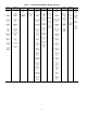
This book contains Start-Up, Controls Operation, Trouble-
shooting and Service information for the 48/50A series
rooftop units. See Table 1. These units are equipped with
ComfortLink™ controls.
Use this guide in conjunction with the separate installation
instructions packaged with the unit. Refer to the Wiring Dia-
grams literature for more detailed wiring information.
Before performing service or maintenance operation on
unit turn off and lock off main power switch to unit.
Electrical shock can cause personal injury and death.
Shut off all power to this equipment during installation
and service. The unit may have an internal non-fused
disconnect or a field-installed disconnect. Note that the
unit may also be equipped with a convenience outlet,
that this outlet is wired to the line side of the unit-
mounted disconnect and will remain hot when the
disconnect in the unit is off. There is a separate fuse/
disconnect for the convenience outlet.
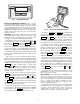
This unit uses a microprocessor-based electronic control
system. Do not use jumpers or other tools to short out com-
ponents or to bypass or otherwise depart from recom-
mended procedures. Any short-to-ground of the control
board or accompanying wiring may destroy the electronic
modules or electrical components.
1. Improper Installation, adjustment, alteration, service, or
maintenance can cause property damage, personal inju-
ry, or loss of life. Refer to the User’s Information Manu-
al provided with this unit for more details.
2. Do not store or use gasoline or other flammable vapors
and liquids in the vicinity of this or any other appliance.
What to do if you smell gas:
1. DO NOT try to light any appliance.
2. DO NOT touch any electrical switch, or use any phone
in your building.
3. IMMEDIATELY call your gas supplier from a neigh-
bor’s phone. Follow the gas supplier’s instructions.
4. If you cannot reach your gas supplier call the fire
department.