
Specifications

3
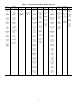
Table 1 — A Series Product Line
LEGEND
The A series units provide ventilation, cooling, and heating
(when equipped) in variable air volume (VAV), variable
volume and temperature (VVT®), and constant volume (CV)
applications. The 48AJ,AK,AW,AY and 50AJ,AK,AW,AY
units contain the factory-installed ComfortLink™ control sys-
tem which provides full system management. The main base
board (MBB) stores hundreds of unit configuration settings
and 8 time of day schedules. The MBB also performs self diag-
nostic tests at unit start-up, monitors the operation of the unit,
and provides alarms and alert information. The system also
contains other optional boards that are connected to the MBB
through the Local Equipment Network (LEN). Information on
system operation and status are sent to the MBB processor by
various sensors and optional boards that are located at the unit.
Access to the unit controls for configuration, set point selec-
tion, schedule creation, and service can be done through a unit-
mounted Scrolling Marquee. Access can also be done through
the Carrier Comfort Network using the ComfortVIEW™ soft-
ware or the accessory Navigator™ hand-held display.
The ComfortLink system controls all aspects of the rooftop.
It controls the supply-fan motor, compressors, and economizers
to maintain the proper temperature conditions. The controls also
cycle condenser fans to maintain suitable head pressure. All
VAV units are equipped with a standard VFD (variable frequen-
cy drive) for supply fan speed control and supply duct pressure
control. The ComfortLink control directly controls the speed of
the VFD based on a static pressure sensor input. In addition, the
ComfortLink control can control the building pressure using
multiple power exhaust fans controlled from damper position or
from a building pressure sensor. The control safeties are contin-
uously monitored to prevent the unit from operating under ab-
normal conditions. Sensors include suction pressure transducers
and saturated condensing temperature sensors which allow for
display of operational pressures and saturation temperatures.
A scheduling function, programmed by the user, controls
the unit occupied/unoccupied schedule. Up to 8 different
schedules can be programmed.
The controls also allow the service person to operate a quick
test so that all the controlled components can be checked for
proper operation.
BASIC CONTROL USAGE
Comfort
Link Control — The ComfortLink control is a
comprehensive unit-management system. The control system
is easy to access, configure, diagnose and troubleshoot.
The control is flexible, providing two types of constant
volume cooling control sequences, two variable air volume
cooling control sequences, and heating control sequences for
two-stage electric and gas systems, and for multiple-stage gas
heating, in both Occupied and Unoccupied schedule modes.
This control also manages:
• VAV duct pressure (through optional VFD), with reset
• Building pressure through two different power exhaust
systems
• Condenser fan cycling for mild ambient head pressure
control
• Space ventilation control, in Occupied and Unoccupied
periods, using CO
2
sensors or external signals, with ven-
tilation defined by damper position or ventilation airflow
measurement
• Smoke control functions
• Occupancy schedules
• Occupancyorstart/stopsequencesbasedonthirdparty
signals
• Alarm status and history and run time data
• Management of a complete unit service test sequence
System diagnostics are enhanced by the use of multiple
external sensors for air temperatures, air pressures and refriger-
ant pressures. Unit-mounted actuators provide digital feedback
data to the unit control.
The ComfortLink control is fully communicating and
cable-ready for connection to the Carrier Comfort Network
(CCN) building management system. The control provides
high-speed communications for remote monitoring via the
Internet. Multiple units can be linked together (and to other
ComfortLink control equipped units) using a 3-wire communi-
cation bus.
The ComfortLink control system is easy to access through
the use of a unit-mounted display module. There is no need to
bring a separate computer to this unit for start-up. Access to
control menus is simplified by the ability to quickly select from
11 menus. A scrolling readout provides detailed explanations
of control information. Only four, large, easy-to-use buttons are
required to maneuver through the entire controls menu. The
display readout is designed to be visible even in bright sunlight.
For added service flexibility, an accessory hand-held
Navigator module is also available. This portable device has an
extended communication cable that can be plugged into the
unit’s communication network either at the main control box or
at the opposite end of the unit, at a remote modular plug. The
Navigator display provides the same menu structure, control
access and display data as is available at the unit-mounted
Scrolling Marquee display.
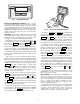
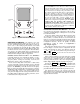
Scrolling Marquee — This device is the keypad inter-
face used to access the control information, read sensor values,
and test the unit. The Scrolling Marquee is located in the main
control box and is standard on all units. The Scrolling Marquee
display is a 4-key, 4-character, 16-segment LED display
module. The display also contains an Alarm Status LED (light-
emitting diode). See Fig. 1. The display is easy to operate using
4 buttons and a group of 11 LEDs that indicate the following
menu structures (see Appendix A):
•RunStatus
• Service Test
•Temperatures
•Pressures
•Setpoints
• Inputs
•Outputs
• Configuration
• Timeclock
• Operating Modes
•Alarms
Through the Scrolling Marquee, the user can access all of
the inputs and outputs to check on their values and status, con-
figure operating parameters plus evaluate the current decision
status for operating modes. Because the A-Series units are
equipped with suction pressure and saturated temperature ther-
mistors, the Scrolling Marquee can also display refrigerant cir-
cuit pressures typically obtained from service gages. The con-
trol also includes an alarm history which can be accessed from
the display. In addition, through the Scrolling Marquee, the
user can access a built-in test routine that can be used at
start-up commissioning and to diagnose operational problems
with the unit.
UNIT APPLICATION
48AJ CV Unit with Gas Heat, Vertical Supply
48AK VAV Units with Gas Heat, Horizontal Supply
48AW CV Unit with Gas Heat, Vertical Supply
48AY VAV Unit with Gas Heat, Horizontal Supply
50AJ CV Unit with Optional Electric Heat, Vertical Supply
50AK VAV Units with Optional Electric Heat, Horizontal Supply
50AW CV Unit with Optional Electric Heat, Vertical Supply
50AY VAV Unit with Optional Electric Heat, Horizontal Supply
CV — Constant Volume
VAV — Variable Air Volume