
Specifications

4
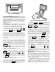
Accessory Navigator™ Display — The accessory
hand-held Navigator display can be used with the 48/50A
units. See Fig. 2. The Navigator display operates the same way
as the Scrolling Marquee device. The Navigator display is
plugged into the RJ-11 jack in the main control box on the
COMM board. The Navigator display can also be plugged into
the RJ-11 jack located on the unit corner post located in the
auxiliary control box.
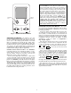
Operation — All units are shipped from the factory with
the Scrolling Marquee display, which is located in the main
control box. See Fig. 1. In addition, the ComfortLink™ control
also supports the use of the handheld Navigator display.
Both displays provide the user with an interface to the
ComfortLink control system. The displays have and
arrow keys, an key and an key. These
keys are used to navigate through the different levels of the dis-
play structure. The Navigator and the Scrolling Marquee oper-
ate in the same manner, except that the Navigator display has
multiple lines of display and the Scrolling Marquee has a single
line. All further discussions and examples in this document will
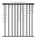
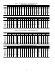
be based on the Scrolling Marquee display. See Table 2 for the
menu structure.
The four keys are used to navigate through the display
structure, which is organized in a tiered mode structure. If the
buttons have not been used for a period, the display will default
to the AUTO VIEW display category as shown under the RUN
STATUS category. To show the top-level display, press the
key until a blank display is shown. Then
use the and arrow keys to scroll through the top-level
categories. These are listed in Appendix A and will be
indicated on the Scrolling Marquee by the LED next to each
mode listed on the face of the display.
When a specific mode or sub-mode is located, push the
key to enter the mode. Depending on the mode, there
may be additional tiers. Continue to use the and keys
and the keys until the desired display item is found.
At any time, the user can move back a mode level by pressing
the key. Once an item has been selected the display
will flash showing the item, followed by the item value and
then followed by the item units (if any).
Items in the Configuration and Service Test modes are
password protected. The display will flash PASS and WORD
when required. Use the and arrow keys to enter the
four digits of the password. The default password is 1111.
Pressing the and keys simultaneously
will scroll an expanded text description across the display indi-
cating the full meaning of each display point. Pressing the
and keys when the display is blank
(MODE LED level) will return the display to its default menu
of rotating AUTO VIEW display items. In addition, the pass-
word will need to be entered again before changes can be made.
Changing item values or testing outputs is accomplished in
the same manner. Locate and display the desired item. If the
display is in rotating auto-view, press the key to stop
the display at the desired item. Press the key again so
that the item value flashes. Use the arrow keys to change the
value of state of an item and press the key to accept
it. Press the key and the item, value or units display
will resume. Repeat the process as required for other items.
If the user needs to force a variable, follow the same process
as when editing a configuration parameter. A forced variable
will be displayed with a blinking “f” following its value. For
example, if supply fan requested (FAN.F) is forced, the display
shows “YESf”, where the “f” is blinking to signify a force on
the point. Remove the force by selecting the point that is forced
with the key and then pressing the and ar-
row keys simultaneously.
Depending on the unit model, factory-installed options and
field-installed accessories, some of the items in the various
Mode categories may not apply.
System Pilot — The System Pilot (33PILOT-01) is a
component of Carrier’s 3V™ system and serves as a user-
interface and configuration tool for all Carrier communicating
devices. The System Pilot can be used to install and commis-
sion a 3V zoning system, linkage compatible air source,
universal controller, and all other devices operating on the
Carrier communicating network.
Additionally, the System Pilot can serve as a wall-mounted
temperature sensor for space temperature measurement. The
occupant can use the System Pilot to change set points. A
security feature is provided to limit access of features for
unauthorized users. See Fig. 3 for System Pilot details.
ESCAPE
ENTER
ESCAPE
ENTER
ENTER
ESCAPE
ENTER
ESCAPE
ENTER
ESCAPE
ENTER
ENTER
ENTER
ENTER
ESCAPE
ENTER
R
u
n
S
ta
tu
s
S
e
rv
ic
e
T
e
s
t
T
e
m
p
e
ra
tu
re
s
P
re
s
s
u
re
s
S
e
tp
o
in
ts
In
p
u
ts
O
u
tp
u
ts
C
o
n
figu
ra
tio
n
T
im
e
C
lo
c
k
O
p
e
ra
tin
g
M
o
d
e
s
A
la
rm
s
ENTER
ESC
M
ODE
A
la
rm
S
ta
tu
s
TIME
EW
T
LW
T
S
ETP
12.58
54.6
° F
44.1
° F
44.0
° F
N
A
V
IG
A
T
O
R
ComfortLink
Fig. 2 — Accessory Navigator Display
Run Status
Service Test
Temperature
Pressures
Setpoints
Inputs
Outputs
Configuration
Time Clock
Operating Modes
Alarms
Alarm Status
ENTER
MODE
ESCAPE
Fig. 1 — Scrolling Marquee