
Specifications

5
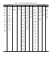
CCN Tables and Display — In addition to the unit-
mounted Scrolling Marquee display, the user can also access
the same information through the CCN tables by using the
Service tool or other CCN programs. Details on the CCN
tables are summarized in Appendix B. The variable names
used for the CCN tables and the Scrolling Marquee tables may
be different and more items are displayed in the CCN tables.
As a reference, the CCN variable names are included in the
Scrolling Marquee tables and the Scrolling Marquee names are
included in the local display tables in Appendix B.
GENERIC STATUS DISPLAY TABLE — The GENERICS
points table allows the service/installer the ability to create a
custom table in which up to 20 points from the 5 CCN
categories (Points, Config, Service-Config, Set Point, and
Maintenance) may be collected and displayed.
In the Service-Config table section, there is a table named
“generics”. This table contains placeholders for up to 20 CCN
point names and allows the user to decide which points are dis-
played in the GENERIC points table under the local display.
Each one of these placeholders allows the input of an 8-character
ASCII string. Using a CCN interface, enter the Edit mode for the
Service-Config table “generics” and enter the CCN name for
each point to be displayed in the custom points table in the order
they will be displayed. When done entering point names, down-
load the table to the rooftop unit control.
Conventions Used in This Manual — The follow-
ing conventions for discussing configuration points for the lo-
cal display (Scrolling Marquee or Navigator™ accessory) will
be used in this manual.
Point names will be written with the Mode name first, then
any sub-modes, then the point name, each separated by an
arrow symbol (→). Names will also be shown in bold and
italics. As an example, the IAQ Economizer Override Position
which is located in the Configuration mode, Indoor Air Quality
Configuration sub-mode, and the Air Quality Set Points
sub-sub-mode, would be written as Configuration
→
IAQ
→
IAQ.SP
→
IQ.O.P.
This path name will show the user how to navigate through
the local display to reach the desired configuration. The user
would scroll through the modes and submodes using the
and keys. The arrow symbol in the path name repre-
sents pressing to move into the next level of the
menu structure.
When a value is included as part of the path name, it will be
shown at the end of the path name after an equals sign. If the
value represents a configuration setting, an explanation will be
shown in parenthesis after the value. As an example, Configu-
ration
→
IAQ
→
AQ.CF
→
IQ.AC =1(IAQ Analog Input).
Pressing the and keys simultaneously
will scroll an expanded text description of the point name across
the display. The expanded description is shown in the local dis-
play tables but will not be shown with the path names in text.
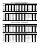
The CCN point names are also referenced in the local
display tables for users configuring the unit with CCN software
instead of the local display. The CCN tables are located in
Appendix B of this manual.
IMPORTANT: The computer system software
(ComfortVIEW™, Service Tool, etc.) that is used to
interact with CCN controls always saves a template of
items it considers as static (e.g., limits, units, forcibil-
ity, 24-character text strings, and point names) after
the software uploads the tables from a control. There-
after, the software is only concerned with run time
data like value and hardware/force status. With this in
mind, it is important that anytime a change is made to
the Service-Config table “generics” (which in turn
changes the points contained in the GENERIC point
table), that a complete new upload be performed. This
requires that any previous table database be
completely removed first. Failure to do this will not
allow the user to display the new points that have been
created and the CCN interface will have a different
table database than the unit control.
ENTER
ESCAPE
ENTER
SCROLL
+
-
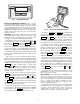
NAVIGATE/
EXIT
MODIFY/
SELECT
PAGE
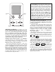
Fig. 3 — System Pilot User Interface