
Installation guide
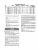

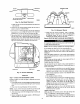
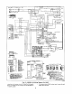
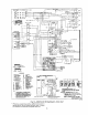
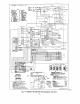
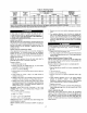
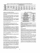
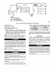

Table 6--Air Delivery (CFM) at Indicated Temperature Rise and Rated Heating Input
HEATING TEMPERATURE RiSE =F
INPUT
(BTUH) 20 25 30 35 40 45 50 56 60 65 70
40,000 1500 1200 1000 857 750 667 600 545 500 -- --
60,000 2250 1800 1500 1286 1125 1000 900 818 750 692 --
90,000 -- -- 2250 1929 1668 1500 1350 1227 1125 1038 964
115_000 -- -- -- 2464 2156 1917 1725 1568 1438 1327 1232
130,000 -- -- -- 2786 2438 2167 1950 1773 1625 1500 --
NOTE: Cashed areas do not fall within the approved temperature rise range of the unit.
AIRFLOW AND TEMPERATURE RISE
The heating section for each size unit is designed and approved for
heating operation within the temperature-rise range stamped on the
unit rating plate.
Table 6 shows the approved temperature rise range for each
heating inpuL and the air delivery CFM at various temperature
rises. The heating operation airflow must produce a temperature
rise that falls within the approved range.
Table 6 shows the approved temperature rise range for each
heating input, and the air delivery CFM at various temperature
rises. The heating operation airflow must produce a temperature
rise that fails within the approved range.
Refer to htdoor Airflow attd Airflow Adjustments section to adjust
heating airflow when required.
HEATING SEQUENCE OF OPERATION-HEAT PUMP
Heat Pump Heating-Sequence of Operation: Outdoor tempera-
ture above balance point setpeint of Thermidistat TM (option l 1).
(See Fig. 15, 16 & 17)
On a call for heating, terminals "Y" and "G" of the Thermidis-
tatTM or Dual Fuel thermostat are energized. The "Y" signal is sent
to the Defrost Board (DB) terminal "Y". The DB has a built in five
minute anti-short cycle timer which will not allow the compressor
to restart before the time delay has expired, "T2" energizes the
compressor eontaetor via the High Pressure Switch (HPS) and
Low Pressure Switch (LPS). The compressor and outdoor fan start.
Thermidistat r_ "G" energizes the Integrated Gas Control (IGC)
tet_thnal '+G". Tile blower motor is energized through the "BM"
and "L2" terminals of the IGC.
When the Thermidista0 M removes the "Y" and +'G" calls, the
compressor contaetor and outdoor fan and evaporator motor are
de-energized.
HEATING SEQUENCE OF OPERATION-GAS HEAT
Gas Heating--Sequence of Operation: Outdoor temperature be-
low balance point setpoint of Thermidistuff M (option 11).
(See Fig. 15, 16 & 17)
On a call for heating, terminal "W" of the Thermidistat TM or Dual
Fuel thermostat is energized, starting the induced-draft motor.
When the hall-eft_ct sensor on the induced-draft motor senses that
it has reached the required speed, the burner sequence begins. This
t_nction is performed by the integrated gas control (IGC). The
indoor-fan motor is energized 45 sec. after flame is established.
When the thermostat is satisfied and '+W" is de-energized, the
burners stop firing and the indoor-fan motor shuts off after a
45-see. time-off delay.
An LED (light-emitting diode) indicator is provided on the control
board to monitor operation. The control board is located by
removing the burner access panel. During normal operation, the
LED is continuously on. (See Table 7 for error codes.)
Table 7--LED Indications
ERROR CODE
Normal Operation
Hardware Failure
Fan On/Off Delay Modified
Limit Switch Fault
Flame Sense Fault
Four Consecutive Limit Switch Faults
Ignition Lockout Fault
Induced-Draft Motor Fault
Rollout Switch Fault
Internal Control Fault
Temporary one hour automatic
reset fault (See note 2)
NOTES:
1.
A.Thereisa 3-sec.pause betweenerror codedisplays.
LED INDICATION
On
Off
1 Flash
2 Flashes
3 Flashes
4 Flashes
5 Flashes
6 Flashes
7 Flashes
8 Flashes
9 Flashes
B. If more than one error code exists, all applicable error COdeS will be
displayed in numerical sequence
C. This chart is on the wiring diagram located inside the burner access panel.
2.
A. This code indicates an internal processor fault that will reset itself in one
bOll=. Fault can be caused by stray RF signals in the structure or nearby. This
is a UL requirement.
B. Wrien W1 is energized the burners will remain on for a minimum el 60
seconds+
LIMIT SWITCHES
Normally closed limit switch (LS)- The limit switch is normally
closed and opens on sensing excessive temperature rise in the heat
exchanger compartment. Should the leaving-air temperature rise
above the maximum allowable temperature, the limit switch opens.
When tile limit switch opens the IGC control circuit instantly
opens the gas valve circuit and stops gas flow to the burners. The
blower motor continues to run until LS resets.
When the air temperature at the limit switch drops to the
low-temperature setting of the limit switch, the switch closes
allows the ignition cycle to restart. The electric-spark ignition
system cycles and the unit returns to normal heating operation.
AUXILIARY LIMIT SWITCH (ROLLOUT)
The function of the switch is to close the main gas valve in the
event of flame rollout. The switch is located above the main
burners. When the temperature at the auxiliary switch reaches the
maximum allowable temperature and opens, the IGC circuit opens,
opening the gas wdve circuit and stopping gas flow to the burners.
The indoor fim motor (IFM) and induced drafi motor continue to
run until switch is reset. The IGC LED will display FAULT CODE
7.
18