
Manual

NOTE: If the unit is being shut down because of a malfimcfion,
call your dealer as soon as possible.
a. Set system SWITCH or MODE contlol to OFF
b. Turn off the electrical power_ install tockoout tag and shut
off gas supply to unit
OPERATING YOUR UNmT
The operation of your system is controlled by the indoor tempera°
ture control (for 48XZ, either a Tl'_ern_idistat TM or dual fuel
thermostat is required) You simply adjust the thermostat and it
maintains the indoor temperature at the level you select. Most
d'_ermostats of heating and cooling systems have 3 controls: a
temperature control selector, a FAN control, and a SYSTEM or
MODE control Refer to your thermostat owner's manual %r more
information.
To better protect your investment and to eliminate unnecessaQ"
service calls, familiarize yourself with the following fi_cts:
1. During heat pump heating, increasing the them_ostat setting
more than 2°F may cause the supplemental gas heat to be
tamed on for a short period of time to satis[}' the thermostat.
Needless use of the supplementary heat reduces potential
energy savings.
2. Ice or frost tends to %rm on the coil during winter heating
operation. Your heat pump is designed to automatically melt
the ice. When in this defrost cycle, it is normal for steam or
fog to rise from the outdoor unit. Do not be alam_ed!
Step 1=Cooling Mode
With the SYSTEM o1"MODE control set to COOL, your unit will
run in cooling mode until the indoor temperature is lowered to the
level you have selected. On extlemely hot days, your unit will run
for longer periods at a time and have shorter "off' periods than on
moderate days.
Step 2--Neat Pump Heating Mode
With the SYSTEM or MODE control of yo_lr indoor thermostat set
to HEAT, your unit will run in heat pump heating mode until room
temperature is raised to the level you have selected. Of course,
your system wil! run fbr longer periods to maintain a com%rtable
environment on cooler days and nights than on moderate ones.
Step a--Gas Heat Mode
Your heat pump is your primary heating source. Yon" system is
also be equipped with a supplemental gas heating source. On cold
days and nights, your system wil! atttomatically mm on the
supplemental heat in order to maintain the level of comfbrt you
have selected.
When your heat pump needs additional heat to keep you comfort°
able, your Carrier electronic theilnostat will mm on the supple°
mental gas heat and display the "AUX HT" message.
Step 4--Defrost Mode
When your heat pump is providing heat to yon" home or office and
the outdoor temperature &ups below 45_T, moisture may begin to
fi'eeze on the suribce of the coil. If allowed to build up, this ice
would impede airflow across the coil and reduce the amount of
heat absorbed fi'om t!-_eoutside air. So, to maintain energyoefi_cient
operation, your heat pump has an automatic deii'ost mode.
The defrost mode starts at a preset time interval of 30 minutes,
although, it may be reset to 60, 90 or 120 minutes. Defrost will
start at the preset time only if the ice is sufficient to interfere with
normal heating operation.
After the ice is melted from the coil, or after a n_axinmm of 10
minutes in defrost mode, the unit automatically switches back to
normal heating operation.
Do not be alarmed if steam or fog appears at the omdoor unit
during defrost mode. Water vapor fi'om the melting ice may
condense into a mist in the cold outside air.
During certain weather conditions such as heavy snow and
freezing rain it is not uncommon fbr ice to build up on the unit
grille. This is nom_al for these weather conditions. Do not attempt
to remove the ice from the unit grille This condition will not affect
the proper function of the unit and will clear within a few days.
Step 5--Emergency Heat Mode
If you shu_dd have problems with the heat pump portion of your
system, this mode allows your supplemental gas heating source to
keep your home or ofi_ce warm until your heat pump can be
serviced.
MAINTENANCE AND SERVmCE
This section discusses maintenance that sho_dd be peKbrmed on
your system. Most maintenance should be performed by your
dealer. You, as the owner, may wish to handle some minor
maintenance for your new unit.
ROUTINE MAINTENANCE
All routine maintenance should be handled by skilled, experienced
personnel. Your dealer can help you establish a standard proceo
dnre.
For your safety, keep the unit area clear and free of combustible
materials, gasoline, and other flammable liquids and vapors.
To assure proper Nnctioning of the unit, flow of condenser air
must not be obstructed from reaching the unit. Clearance _i'om the
top of the unit is 48 in. ( learance of at least 36 in. is required on
sides except the power entry side (42 in. clearance) and the duct
side (12 in. n_inimum clearance).
MAINTENANCE AND (?ARE FOR THE EQUIPMENT
OWq'qER
Before proceeding with those things you might want to maintain
yoursel£, please care*idly consider the %ltowing:
1. TURN OFF ALL ELE(TRI(AL POWER TO YOUR
UNIT AND INSTALL LOCK-OUT TAG BEFORE SER-
VICING OR PERFORMING MAINTENANCE. ELEC-
TRIC SHOCK (OULD (AUSE SERIOUS INJURY OR
DEATH.
2 When removing access panels or perforating maintenance
fmlctions inside your unit, be aware of sharp sheet metal
parts and screws. Although special care is taken to keep
sharp edges to a mininmm, be extremely caret:t_l when
handling parts or reaching into the unit.
Air Filters
The air filter(s) should be checked at least every 3 or 4 weeks and
changed or cleaned whenever it becomes dirty. Dirty filters
produce excessive stress on the blower motor and can cause the
motor to overheat and shut down.
This unit must have air filters in place befbre it can be operated
These filters can be located in one of at least two places. In many
applications ff*e installer will provide return air filter grilles
mounted on the wall or ceiling of the conditioned structure. In the
instance of filter grilles, the filters can simply be removed fi'om the
grille and replaced.
The other typical application is an accessul 7 filter rack installed
inside the unit itsetfl The following information is given to assist
in changing filters used in these internal filter racks.
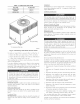
Table 1 indicates the correct tilter size for your unit. Refer to Fig.
2 to access filters installed in the accessory filter rack.