
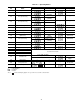
Specifications

3. Remove the 4-pin female plug from the fuse and control
circuit breaker bracket in the main control box, and con-
nect the wires as follows:
a. Insert and secure the red (1) wire to terminal 1 of the
4-pin plug.
b. Insert and secure the white (ground) wire to terminal
2 of the 4-pin plug.
c. Insert and secure the black (2) wire to terminal 3 of
the 4-pin plug.
4. Insert the plug into the existing 4-pin mating connector
on the fuse or control circuit breaker bracket in the main
control box.
IMPORTANT: A shorted CCN bus cable will prevent
some routines from running and may prevent unit from
starting. If abnormal conditions occur, unplug the con-
nector. If conditions return to normal, check CCN con-
nector, and run new cable if necessary. A short in one
section of the bus can cause problems with all system
elements on the bus.
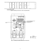
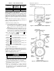
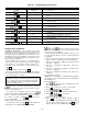
RJ11 Plug Wiring — Units on the CCN can be moni-
tored from the space at the sensor through the RJ11
connector, if desired. To wire the RJ11 connector into the
CCN (Fig. 35):
IMPORTANT: The cable selected for the RJ11 con-
nector wiring MUST be identical to the CCN commu-
nication bus wire used for the entire network. Refer to
Table 41 for acceptable wiring.
1. Cut the CCN wire and strip ends of the red (1), white
(ground), and black (2) conductors. (If another wire color
scheme is used, strip ends of appropriate wires.)
2. Insert and secure the red (1) wire to pin J2 of the space
temperature sensor terminal block (TB1).
3. Insert and secure the white (ground) wire to pin J3 of the
space temperature sensor TB1.
4. Insert and secure the black (2) wire to pin J5 of the space
temperature sensor TB1.
5. Connect the other end of the communication bus cable to
the remainder of the CCN communication bus at the
COMM1 plug located on the fuse and control circuit breaker
bracket in the unit main control box.
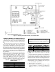
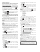
LEGEND
PIC — Product Integrated Control
Fig. 34 — CCN Communication Wiring
43