
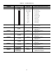
Specifications


ADAPTIVE OPTIMAL STOP (CV Applications Only) —
Optimal stop is used to allow space temperature to drift to
an expanded occupied set point during the last portion of an
occupied period. The control calculates a stop time offset,
(the time in minutes prior to the scheduled unoccupied time)
during which expanded heating and cooling set points can
be used. Adaptive optimal stop utilizes space temperature,
an expanded occupied set point, and a ‘‘K’’ factor to calcu-
late stop time offset. The amount (F) to expand the occupied
set point is user configurable. Like adaptive optimal start,
the control corrects itself for optimal operation by adjusting
the ‘‘K’’ factor as required.
HEATING
NOTE: The heating algorithms on the units will only run
when the supply-air (evaporator) fan is on. Two-stage factory-
installed gas heat is standard on the 48FP,JP,NP units.
When the unit is in the Heating mode, room terminals must
be fully open. The room terminals should be controlled by
the heat interlock relay (HIR) function on VAV applications.
NOTE: HIR not applicable on units using DAV applications.
During heating, the economizer dampers will be at the mini-
mum damper position during Occupied Heating mode, and
will be fully closed during unoccupied heating.
Occupied VAV Operation — Heating is primarily used for
morning warm-up or occupied space heating with the heater
being staged to maintain desired return-air temperature. If
the unit is in morning warm-up, the return-air temperature is
read and compared to the occupied heating set point. The
unit controls will compare the calculated supply-air tem-
perature set point to the actual supply-air temperature to com-
pute the number of stages required to satisfy the conditions.
Once morning warm-up is completed and the unit is in
Occupied mode, heat will not be activated again unless the
Occupied Heating mode has been selected.
Occupied CV Operation — The heater is staged to prevent
the occupied space temperature from falling below the de-
sired set point. The control reads the space temperature and
computes the supply-air temperature necessary to heat the
space to the heating set point. The unit controls will com-
pare the calculated supply-air temperature set point to the
actual supply-air temperature to compute the number of stages
required to satisfy the conditions.
Morning Warm-Up (VAV Only) — Morning warm-up oc-
curs when the adaptive optimal start (AOS) algorithms start
the unit before the occupied start time, and the unit has a
heating demand. The morning warm-up control uses the oc-
cupied heating set point for controlling heat stages. Once the
return air reaches the set point, heating will be shut off.
When the heating demand is satisfied, the warm-up con-
dition will terminate. The unit may reenter morning warm-up
if there is another call for heat before the start of the occu-
pied period. Morning warm-up can continue into the occu-
pied period as long as there is a need for heat, even if oc-
cupied heating is not enabled.
NOTE: The economizer dampers will be fully closed during
morning warm-up, except when morning warm-up contin-
ues into the occupied period. If morning warm-up continues
into the occupied period, the dampers will open to the mini-
mum position to provide ventilation air.
Room terminals must go to the fully open position when
the unit enters the heating mode. The terminals should be
controlled by the HIR function. When the unit goes into heat-
ing mode, the HIR contacts are energized which open the
room terminals.
NOTES:
1. Morning warm-up is initiated before the unit schedule des-
ignated occupied time.
2. HIR is not applicable on units using DAV applications.
Economizer Minimum Position — The control has the ca-
pability of maintaining the minimum economizer position
based on 3 inputs. The 3 inputs are minimum position,
outdoor-air cfm, and IAQ set points. The VENT
function is used to configure the control for the min-
imum position of the economizer.
Indoor-Air Quality (IAQ) — The unit may be configured to
control the occupied space indoor-air quality by maintaining
a constant cfm of outdoor air and/or an allowable level of
undesirable gases or vapors (CO
2
, CO, formaldehyde, etc.)
with installation of appropriate sensors and/or accessories.
The economizer dampers will modulate to maintain the user-
defined set points.
An alert will be generated after 10 minutes if the air qual-
ity level has not been reduced below the set point.
The indoor air quality feature has 3 priority levels as fol-
lows (Refer to Indoor Air Quality (IAQ) and Outdoor Air
Control (OAC) sections on pages 25 and 26 for more
details):
Priority Level 1 — This is the highest level of priority for
indoor air quality. When the IAQ set point is exceeded, the
IAQ algorithms adjust the economizer damper position to
purge the controlled space of CO
2
or other contaminants.
Priority Level 2 — This is a medium level priority and pro-
vides for some occupied space comfort overrides. The IAQ
algorithms adjust the economizer damper position to purge
the controlled space of CO
2
or other contaminants. How-
ever, the following comfort overrides may take precedence:
• space temperature
• supply-air temperature (VAV)
• space humidity
Priority Level 3 — This is the lowest priority level. When
the IAQ set point is exceeded, an alert is generated. Alert
can be viewed at the HSIO and is broadcast on the CCN
network (if applicable), but no other action is taken.
NOTE: Consult the latest updated issue of ASHRAE (Ameri-
can Society of Heating, Refrigeration, and Air Conditioning
Engineers) Standard 62 when determining required set points
for indoor air quality (ASHRAE 62, Ventilation for Accept-
able Indoor-Air Quality section).
Head Pressure Control — The microprocessor con-
trols the condenser fans to maintain the lowest condensing
temperature and the highest operating efficiency possible. The
condenser fan stages are configured to react to either satu-
rated condensing temperatures (SCT) or refrigerant pressure
sensors, or can be controlled by the lead compressor.
Unit sizes 034-038 have 2 stages of fan control. The stage
2 fan contactor OFC1 will cycle in response to the higher
SCT of the 2 circuits. Unit sizes 044-074 have 3 fan stages.
Fan contactors OFC1 and OFC2 will respond to their asso-
ciated circuit SCT.
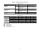
A low ambient head pressure control option is also in-
cluded standard on all units as an additional feature to allow
fan cycling on the first stage. The first stage of head pressure
control is cycled in the same manner as the Motormastert II
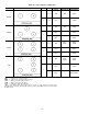
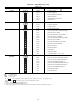
control. See Table 48.
The highest SCT is used to control the condenser (out-
door) fan motor(s) (OFM) controlled by the head pressure
control relay (MMR). See Table 49 for fan control points. If
either stage 2 contactor (OFC1 or OFC2) is energized in ad-
dition to MMR, then MMR will be locked in the energized
mode.
The 2 other stages of head pressure control are controlled
by the SCT on standard units, or the SCT and suction trans-
ducers on units equipped with suction pressure transducers
and suction sensors. Table 49 shows the fan configurations
and lists the on and off points for OFC1 and OFC2.
Table 49 also describes the fan sequence of operation and
defines the particular fans controlled by stage.
54