48FP,JP,NP034-074 50FB,FP,JB,JP,NB,NP034-104 Single-Package Heating/Cooling Units With Product Integrated Controls 50/60 Hz Controls Operation and Troubleshooting CONTENTS Page SAFETY CONSIDERATIONS . . . . . . . . . . . . . . . . . . . . . . 2 GENERAL . . . . . . . . . . . . . . . . . . . . . . . . . . . . . . . . . . . . . . 2-4 Carrier Comfort Network System Architecture. . . . . . . . . . . . . . . . . . . . . . . . . . . . . . . . . . . . 2 PIC Rooftop Information. . . . . . . . . . . . . . . . . . .
CONTENTS (cont) equipment location (roof, elevated structures, etc.). Only trained, qualified installers and service mechanics should install, start up, and service this equipment When working on this equipment, observe precautions in the literature; on tags, stickers, and labels attached to the equipment, and any other safety precautions that apply. Follow all safety codes. Wear safety glasses and work gloves.
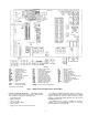
CCN BUS ROOFTOP UNIT ROOFTOP UNIT PIC PIC BUILDING SUPERVISOR NETWORK OPTIONS ROOFTOP UNIT ROOFTOP UNIT PIC PIC HEATING/COOLING UNITS REMOTE CCN SITE AUTODIAL GATEWAY TO ADDITIONAL TERMINALS TERMINAL SYSTEM MANAGER PIC TCU ROOFTOP UNIT DAV AIR TERMINAL TCU TCU DAV AIR TERMINAL NON CARRIER HVAC EQUIPMENT COMFORT CONTROLLER CCN DAV HVAC PIC TCU — — — — — AIR DISTRIBUTION-DIGITAL AIR VOLUME CONTROL (DAV) LEGEND Carrier Comfort Network Digital Air Volume Heating, Ventilation, and Air Cond
The PIC controls are modular and use a processor module (PSIO1), 2 relay modules (DSIO1 and DSIO2), a control options module (PSIO2), and an accessory field-installed keypad and display module (HSIO). The PIC units can operate either in a stand-alone mode or they can be interfaced with the Carrier Comfort Network (CCN). When being installed in network applications, the unit is connected to the CCN communications bus with fieldinstalled cable.
LEGEND CB CCB CH CLO COMP CR DPT DSIO DU ECON EQUIP FU GND HIR — — — — — — — — — — — — — — Circuit Breaker Control Circuit Breaker Crankcase Heater Compressor Lockout Compressor Control Relay Duct Pressure Transducer Module Relay Dummy Terminal Economizer Equipment Fuse Ground Connection Heat Interlock Relay HPS HR IDC IFC IFM IGV LPS MM MMC NEC OAT OFC OFM PEDM — — — — — — — — — — — — — — High-Pressure Switch Heater Relay Induced-Draft Contactor Indoor-Fan Contactor Indoor-Fan Motor Inlet Guide Vanes
the airflow supplied by the unit supply fan and provides the PSIO1 module with a 10-vdc discrete signal for fan status. CHECK FILTER PRESSURE SWITCH — The Check Filter Switch (CFS) is a snap-acting SPDT switch. When dirty filter elements cause the pressure drop across the filter section to exceed the switch setting, the switch contacts close and send a discrete signal (5 vdc) to the PSIO1 module.
LEGEND NEMA — National Electrical Manufacturers’ Association Fig. 3 — Space Temperature Sensor (T-55) LEGEND NEMA — National Electrical Manufacturers’ Association Fig. 4 — Space Temperature Sensor (T-56) NOTE: Sizes 034-074 also require the installation of the control options module (PSIO2), available as a factoryinstalled option or field-installed accessory. OUTDOOR AIR VOLUME CONTROL — This feature ensures a continuous supply of outdoor air to the unit and the occupied space.
NOTE: Sizes 034-074 also require the installation of the control options module (PSIO2), available as a factoryinstalled option or field-installed accessory. CONTROLS AND FUNCTIONS The internal logic circuits of the PIC controls consist essentially of seven sets of control loops that provide direction and control for the major unit systems.
another control function (example: Fire Shutdown) or by service personnel in order to achieve an override or test function. GAIN — A parameter or correction factor used in a control loop calculation that adjusts the responsiveness and sensitivity of the control loop. Accessing the Control System (HSIO) KEYPAD AND DISPLAY MODULE (HSIO) — The keypad and display module HSIO (human sensory input/output) is a field-installed accessory. The HSIO provides unit function information at the unit. See Fig. 8.
Table 3 — HSIO Keypad and Display Module Functions and Subfunctions FUNCTIONS SUB FUNCTION NO.
Table 4 — Accessing Functions and Subfunctions OPERATION KEYPAD ENTRY DISPLAY DESCRIPTION To access a function, press the subfunction number and the function name key. The display will show the subfunction group. STAGES Current stages To move to the other elements, scroll up or down using the arrow keys.
Table 7 — Configuring Units of Measure in Display DESCRIPTION HOW TO CONFIGURE Select Units of Measure SET POINT UNITS Basic System Functions — The unit control system provides over 35 separate unit system and unit control functions. Descriptions of these functions (including purpose of the function, necessary additional hardware, configuration, and operating sequence) have been arranged into 11 separate groups, with each group representing similar topics.
Sequence of Operation, Occupied Cooling (CV) — The economizer cycle must not be permitted or, if permitted, the outdoor air damper position must be open to 90% or higher. The supply fan must be ON for cooling control to operate. The Master Loop will survey Space Temp and Space Temp Offset inputs, then calculate CCSR value. The CSL surveys actual SAT, then calculates number of capacity stages required to satisfy space load. Stages of cooling capacity are initiated. (From zero stages, there will be a 1.
Table 9 — Configuring Fan Operation (CV) DESCRIPTION HOW TO CONFIGURE Select Auto or Continuous Operation (CV only) *If value changed, enable Data Reset before leaving SET POINT RANGE FANM Auto = 0; Cont = 1* .
Loop (CSL) (at high limit value). This will drive cooling stages back to zero stages (at minimum time delay between stages). Simultaneous operation of heating and cooling cycles may be observed during transition. Once OHSP is satisfied by RAT, heating will terminate and cooling cycle will restart. The Reheat function will activate Heating control with concurrent operation of compressor stages.
Configuration — To configure Alert set points, press to enter the Alert Limits subfunction. Scroll to the desired alert. Enter new value. See Table 14 for default values and available ranges. See Table 15 for alert reset criteria. To enable Occupied Heating (VAV units) press . Enter the password. Press to enter into the User Configuration subfunction. Scroll down to OHEN (Occupied Heating Enable). The current configuration will be displayed (0 = disabled, 1 = enabled). The default is disabled.
Table 14 — Sensor Set Point Alert Limits, Ranges, and Default Values NAME DESCRIPTION SUBFUNCTION BP IAQ OAC OARH OAT RAT* RH* SAT* SP* SPT* OCCUPIED SPACE STATUS ALERT DEFAULT (LOW) ALERT DEFAULT (HIGH) LOW LIMIT HIGH LIMIT Occupied –0.25 in.wg 0.25 in.wg –0.5 in.wg 0.5 in.
Schedules Group — This group includes Schedule I Configuration — To configure: 1. Connect control wires from external controlled device at PSIO2 Channel 44 (terminals J6/41 and J6/42). 2. Enter Time Schedules. Press . (See Schedule Function section on page 52 for detailed instructions.) Define Period 1 (Occupied, Unoccupied). Define Periods 2 thru 8 (as required). and II, Timed Discrete Output, Timed Override, Adaptive Optimal Start, and Adaptive Optimal Stop (available on CV units only).
OPTIMAL START — The control will compute a time period (in minutes) to start Occupied Mode Warm-up prior to start of the Occupied Mode schedule, to arrive at Occupied set points just as Occupied period begins. Optimal Start is Mode 26. Optimal Start is allowed only if the RAT is less than Occupied Heating Set Point (VAV units), or if the space temperature is less than the Occupied Heating Set Point (CV units).
Economizer and Power Exhaust Group — This enthalpy switch. This sensor (reference Part Number HC57AC078) is installed in the return air duct and is wired directly to the factory-installed enthalpy switch (see Fig. 9). When the enthalpy control determines that the outdoor air enthalpy is lower than the return air enthalpy, the enthalpy switch closes (at Channel 10), signaling the base unit control to use the economizer as first stage of cooling control immediately.
RH Sensor Configuration for Differential Enthalpy — To configure the RH sensors for differential enthalpy, press to enter into the Service function. Enter the password. Press to enter into the User Configuration subfunction. Scroll down to HUSN. The current configuration will ENTER to conbe shown. The default is 0 (no sensor). Press figure the control for two sensors. Economizer Algorithms — See Table 18 for economizer operation definitions.
O ENTHALPY CONTROLLER When Nighttime Free Cooling is initiated, the economizer dampers drive full open. The supply fan runs until the space temperature drops below NTSP or space temperature drops below (OAT + 3 F). When the conditions are met, the economizer dampers close and the fan shuts off. Configuration — To enable Nighttime Free Cooling, press to enter into the Service function. Enter the password. Press to enter into the User Configuration subfunction. Scroll down to NTEN.
If space pressure decreases until PEDM position is reduced to 10% of open position, PEDM2 will open, deenergizing fan contactor PEC2 and auxiliary control relay PER, and shutting off fan no. 2. If BP is less than BPSP – BPSO for 4 to 6 minutes, with the power exhaust damper at minimum position, the exhaust fan will be turned off and the BPSR will be set to its minimum value. See Table 23. NOTE: Power exhaust has a 2-minute minimum off-time to minimize cycling.
Smoke Control Group — This group includes Pressurization, Evacuation, Smoke Purge, and Fire Shutdown. PRESSURIZATION — Pressurization mode is used to prevent entrance of smoke into the conditioned space in the event of fire or other emergency condition. The pressurization function activates in response to closure of external signal contact set. The function also initiates an alarm signal to CCN Building Supervisor. Pressurization is Mode 34. See Table 24.
Special Ventilation Group — This group includes In- High Humidity: If unit is equipped with humidity sensors and RH > HHL, the IMP = 0 and economizer will close to MDP. The Economizer Submaster Loop will determine economizer damper position (IQMP) based on higher of IMP or MDP. 6. If IAQ not required, then the unit control sets IMP at 0. The economizer remains at MDP position. 7. If IAQ is Priority 3 (low) and an IAQ sensor is connected, the control will evaluate IAQ sensor value.
IAQ (Pre-Occupancy) PURGE — If outdoor air conditions permit, IAQ Pre-Occupancy Purge will open economizer and energize supply fan 2 hours before next Occupied period, to provide complete exchange of indoor air with fresh air. Duration of purge mode is user-configured (typically 5 minutes). The IAQ Purge is Mode 28. See Table 27. The factoryinstalled economizer option is required. Sequence of Operation — The IAQ Purge will operate only if the following conditions exist: • Economizer installed and enabled.
Table 28 — Configuring IAQ (Pre-Occupancy) Purge DESCRIPTION HOW TO CONFIGURE AT HSIO RANGE PURG Enable Purge NOTE: The following user-configured options require use of Service Tool or CCN ComfortWORKS software to change. 2. Select Purge Duration period. Change IQPD set point. Default is 5 minutes. Range is 5 to 60 minutes. 3. Select Low Temperature Minimum Position. Change LTMP set point. Default is 10%. Range is 0 to 100%. 4. Select High Temperature Minimum Position. Change HTMP set point.
Sequence of Operation — If the supply fan is off, all modes are deactivated and the heating control valves are closed. For IAQ Reheat to be active: IQMP > MDP and OAT < SASP. When IAQ Reheat is active, control will issue 4 to 20 mA signal (at Channel 43) to hydronic heat control valve, to maintain SAT control temp (IAQRR) at Supply Air sensor location. Configuration — To configure, enable IAQ Mode (see IAQ section for configuration) or enable OAC Mode (see OAC section for configuration).
Table 33 — Configuring Dehumidification and Reheat DESCRIPTION HOW TO CONFIGURE AT HSIO Set Dehumidification Set Point (“High Humidity Override”) SET POINT RANGE HHL 0 to 100% NOTE: If Unit Type is VAV, unit must be configured for Occupied Heating Enabled (see Table 13, Configuring Heating). HUMIDIFIER CONTROL — There are 2 types of Humidifier control functions available with these units: Analog-output control or Discrete-output control.
To set the Static Pressure set point, press to enter into the Set Point function and the Set Point subfunction. Scroll down to SPSP. The current set point will be shown. The default is 1.5 in. wg. The acceptable range of values is 0.0 to 5.0 in. wg. To change the set point, enter the new number (example: ) and press ENTER . See Table 36. To configure the Supply Air Temperature Reset Limit, press to enter into the Space Temperature Reset Configuration subfunction. Scroll down to LMIT (Reset Limit).
Remote Controls Group — This group includes Remote Start (Occupied/Unoccupied status control) and Space Temperature Offset (CV only). REMOTE START — The Remote Start function allows a general-purpose building/energy management system to signal the unit to switch between Unoccupied and Occupied modes from a remote location. This function will also override a Standby command status by initiating an Occupied mode. Upon removal of remote signal, unit will switch to Unoccupied mode.
Table 39 — Configuring Hydronic Heating DESCRIPTION HOW TO CONFIGURE AT HSIO SET POINT RANGE Select Heat Type HEAT Hot water/Steam = 1*, None = 0 Opt: Enable Occupied Heating OHEN Enable = 1; Disable = 0 Occupied Heating Set Point OHSP 55 to 80 F (13 to 27 C) Unoccupied Heating Set Point UHSP 40 to 80 F (4 to 27 C) HCFO 35 to 65 F (2 to 18 C) Select Heating Set Points: (Use ComfortWORKS® software) Select Heat Coil Fan Off Set Point *If value changed, enable Data Reset before leaving.
Table 41 — Configuring Head Pressure Control (Motormaster Control) DESCRIPTION HOW TO CONFIGURE AT HSIO SET POINT RANGE Disable ‘‘Motormaster’’ MMAS Disable = 0; Enable = 1 Adjust Head Pressure Set Point HPSP 80 to 150 F (27 to 65 C)* *If value changed, enable Data Reset before leaving . Configuration — To configure: 1. Enable Demand Limit. Press to enter the subENTER function. Scroll down to DLEN. Press to enable.
Optimal Start Routine — The following TSM points are used in the optimal start portion of the rooftop unit PIC adaptive optimal start/stop routine (AOSS): AZT, NEXTOCCT, NEXTOCCD, PREVUNOT, and PREVUNOD from the TSM. The rooftop PIC uses this information to calculate a bias time that is then used by both the rooftop PIC and the TSM. When the current time of day is greater than the biased start time, the rooftop PIC uses the AOZT from the TSM to determine when the occupied set point has been achieved.
to go to the Minimum Heating position when the unit goes into the unoccupied or occupied heating mode. The HIR function is provided for this control. When the unit goes into heating mode, the contact set at Channel 60 (DSIO2) is energized to provide switch closure or opening (depending on how the field-supplied power source is set up) to open the room terminals.
RED BLK RED BLK SIZES SIZES 034-048 054-104 TB3 TB2 1 1 3 2 RED RED RED BLK BLK BLK TO PROCESSOR MODULE NO. 1 SENSOR 1 SENSOR 2 SENSOR 3 SENSOR 4 SPACE TEMPERATURE AVERAGING — 4 SENSOR APPLICATION SIZES 034-048 TB3 1 SIZES 054-104 TB2 3 2 1 RED RED BLK BLK RED BLK LEGEND — Terminal Block Factory Wiring Field Wiring SENSOR 1 RED RED BLK BLK SENSOR 4 BLK NOTE: Sensor Part No. is CEC0121448-01. SENSOR 3 SENSOR 2 SENSOR 5 SENSOR 6 RED TB RED BLK TO PROCESSOR MODULE NO.
LEGEND DSIO — Relay Module Fig. 18 — Remote START/UNOCCUPIED Control LEGEND DSIO — Relay Module Fig. 17 — Differential Enthalpy Sensor Fig. 18 — Remote START/UNOCCUPIED Control ACCESSORY OUTSIDE AIR RELATIVE HUMIDITY GRA PSIO NO. 2 CH. 33 VIO 2 1 J2 24V J1 2 1 FIELD-SUPPLIED 24-V ISOLATED POWER SUPPLY TB4 BLU 3 1 2 J2 CH.
SIZES 034-048 TB2 SIZES 054-104 TB2 14 5 J7 SW-2 19 SW-4 22 SW-3 25 SW-1 28 PSIO NO. 2 SIZES 054-104 SIZES 034-048 SW-5A TB3 4 HIR TB3 4 4 SW-5B 6 TB3 TB2 5 8 TB3 TB2 2 8 4 SW-5B 6 REMOVED FROM TB2-10 SWITCH CONFIGURATION VOLTAGE SW-1 N.O. 24 SW-2 N.O. 24 Activate Pressurization Mode SW-3 N.O. 24 Activate Evacuation Mode SW-4 N.O. 24 Activate Smoke Purge Mode SW-5 A/B A: N.O. B: N.C.
TO 24-V ISOLATED TRANSFORMER BRN OUTDOOR AIR + 24V RED 24V - PSIO NO. 2 J6 PNK BLK PSIO NO. 2 CH. 35 + 37 HYD VLV CFM ACY - 38 LEGEND HYDRONIC VALVE ACTUATOR Terminal Block TB — Field Wiring LEGEND Component Terminal Terminal Block TB — Terminal Block Terminal Field Wiring Fig. 22 — Outdoor Airflow Control Component Terminal Fig. 25 — Hydronic Heating PSIO NO. 2 J6 PSIO NO. 2 J7 41 31 SIZES 034-048 SIZES 054-104 TB2 TB2 14 5 LEGEND 42 RELAY PART. NO.
PSIO NO.
Timed Discrete Output — A timed discrete output is available for switching on and off items such as parking lot lights. Time Schedule II ( SCHD to SCHD) operates this function. A special relay (part no. HK35AB001) with a 20 vdc holding coil must be field wired. See Fig. 23. Air Pressure Tubing — Before options such as inlet guide vanes (IGV), variable frequency drive (VFD), and/or modulating power exhaust can operate properly, the pneumatic tubing for pressure sensing must be installed.
Fig. 31 — Auxiliary Control Box Location; Size 054-104 Units BP DP PL PS — — — — Fig.
BP CF DP FS PECB PEC — — — — — — LEGEND Building Pressure PER Check Filter PS Duct Pressure RFC Fan Status RFCB Power Exhaust Circuit TB Power Exhaust Contactor — — — — — Power Exhaust Relay Pressure Switch Return Fan Contactor Return Fan Circuit Breaker Terminal Block Fig.
2. Cut the CCN wire and strip the ends of the red (+), white (ground), and black (–) conductors. (If a different network color scheme is used, substitute appropriate colors.) 3. Remove the 4-pin female plug from the fuse and control circuit breaker bracket in the main control box, and connect the wires as follows: a. Insert and secure the red (+) wire to terminal 1 of the 4-pin plug. b. Insert and secure the white (ground) wire to terminal 2 of the 4-pin plug. c.
CCN COM COMM GND SW T TH — — — — — — — LEGEND Carrier Comfort Network Common Communications Ground Switch Terminal Thermostat, Heating *Constant volume applications only. Fig. 35 — Space Sensor to Communication Bus Wiring Appendix C contains a list of all available points that are accessible via DataPort and DataLink devices.
START-UP The switch must be set prior to unit operation. To set the switch, turn the adjustment screw on top (center) of switch slowly clockwise to find the "pivot" point where the filter status still reads clean under in the HSIO display. Initial Check IMPORTANT: Do not attempt to start unit, even momentarily, until all items on the Controls Start-Up Checklist (in installation instructions) and the following steps have been completed.
3. Adjustments should be made to the blue cam only. The pointer on the red cam should remain centered and at the top, as this will deenergize motor no. 2 properly. 4. Each click of the blue cam changes the switch setting by approximately 3 degrees of travel. 5. If motor no. 2 was energized too soon (Step 4 of the test above was yes), turn blue cam one click to left (see Fig. 37). If motor no. 2 was not energized (Steps 4 and 5 of the test above were no), turn blue cam one click to the right (see Fig. 37).
In the following example, demand limit will be enabled, and the loadshed set point will be set at 60% of available capacity. 1. Press . 2. Press ENTER 3. Press . The CONFIGURATION. 4. Press DSB. Press to scroll to the next display (the current date in month, date, and year format). The month is also entered as a number: 1 = January, 2 = February...12 = December. . (This is the login command.) display will read In the following example, the day, time, and date will be set.
Table 46 — Set Point Directory SET POINT Subfunction Keypad Entry Display 1 SET POINTS SET POINT 2 DEMAND SETPOINTS OHSP X Occupied heat set point X OCSP X Occupied cool set point X UHSP X Unoccupied heat set point X UCSP X Unoccupied cool set point X SPSP X Static pressure set point X SASP X Supply air set point X HUSP X Humidity set point X DEMAND 3 DATE AND TIME 5 HOLIDAY TIMES LEGEND dd dur mm — Day — Duration — Month 49 Demand limit set points LSP X Loadshed set point X TIM
Table 47A — Set Point Ranges and Defaults (English Units) BPSP DISPLAY SET POINT DESCRIPTION Building pressure set point DEFAULT VALUE ALLOWABLE RANGE 0.05 in. wg ECSO* Economizer set point offset 3F 0 to .50 in.
Table 48 — Operating Modes TO CONFIGURE OPTION TO ENABLE MODE MODE NO.
Table 49 — Setting Daylight Savings Time KEYBOARD ENTRY ENTER ENTER ENTER ENTER ENTER ENTER DISPLAY COMMENTS DAYLIGHT Daylight savings time field configuration of set point function ENM X Month when daylight savings time begins ENM 4 Daylight savings time configured to start month 4 (April) END X Day of month when daylight savings time begins END 16 Daylight savings time configured to start on the 16th of the month ENT X Time of day when daylight savings time begins ENT 2.
7. Scroll through the rest of the days (press ) to to be sure that no other days have been flagged. Suppose, for this example, Tuesday was flagged for this period. To ENTER , change this period from YES to NO, press and the display will change to TUE NO. Subfunctions through of optional discrete output (schedule II). define schedule NOTE: If the unit is connected to a DAV system, the unit time schedule is ignored.
Table 50 — Schedule Directory Subfunction Keypad Entry SCHEDULE Display 1 OVERRIDE OVRD xHR Comments Number of Override Hours (0 to 4 Hours); Schedule I 2 PERIOD 1 PERIOD 1 Period 1; Time Schedule I OCC HH.MM Occupied Time UNO HH.
Reset command, then issue Cooling Coil Submaster Reference (CCSR) to Cooling Submaster Loop (CSL). 3. The CSL surveys actual SAT, then calculates number of capacity stages required to produce the CCSR leaving the unit. 4. Stages of cooling capacity are initiated. From zero stages, there will be a 1.5 to 3 minute delay before the first stage is initiated. The time delay between stages in increasing demand is 90 seconds. 5. As actual SAT approaches CCSR value, stages are released.
2. HIR is not applicable on units using DAV applications. Economizer Minimum Position — The control has the capability of maintaining the minimum economizer position based on 3 inputs. The 3 inputs are minimum position, outdoorair cfm, and IAQ set points. The VENT function is used to configure the control for the minimum position of the economizer. time in minutes prior to the scheduled unoccupied time) during which expanded heating and cooling set points can be used.
Sizes 088 and 104: The SCT is used to control the condenser (outdoor) fan motor(s) (OFM) controlled by the head pressure control relay (MMR) for each circuit. See Table 52 for fan control points. If outdoor fan is energized in addition to Motormaster® control, then Motormaster control will be locked in the energized mode.
Table 51B — Head Pressure/Fan Cycling Control (088 and 104 Sizes) UNIT CONFIGURATION MOTOR LOCATION CIRCUIT: MOTOR ID NO.
Table 52 — Fan Sequence of Operation UNIT SIZES FAN ARRANGEMENT STAGE CIRCUIT FAN RELAY OUTPUT RELAY CONTROLLED FAN(S) CONTROLLED 1 Com MM MMC OFM1 2 Com OFC1 — OFM2 1 Com MM MMC OFM2 1 OFC1 — OFM1 2 OFC2 — OFM3 Com MM MMC1 MMC2 OFM3 OFM4 1 OFC1 — OFM1 2 OFC2 — OFM2 Com MM MMC1 MMC2 OFM3 OFM5 1 OFC1 — OFM1 2 OFC2 — OFM2, OFM4 1 MMR-A MMC-A OFM5 2 MMR-B MMC-B OFM6 1 OFCA — OFM1, OFM3 2 OFCB — OFM2, OFM4 034-038 044,048 2 1 054,064 2 1
Control Loop Checkout 5. Verify/adjust the SMG. If the SMG is too large, the loop will tend to oscillate (hunt). If it is too small, the loop will react too slowly. Verify or adjust the SMG as follows: Using the HSIO keypad, force the submaster reference of the control loop to a value above or below the actual sensor reading. Verify that the actuator responds correctly. If the actuator drives in the wrong direction, go to the submaster gain (SMG) for the control loop and reverse the sign of the gain.
If the submaster droop is negative (actual value less than reference value), the SCV should be increased for HCV and IGV loops and decreased for CC and ECON loops. 8. Once the submaster loop is adjusted, remove all forced values and proceed with verification and adjustment of master loop. 9. To check the master loop: Create a demand in the master loop. For example: Force the actual space temperature to a value less than the heating set point or greater than the cooling set point. 10.
operation, this will be the MSAS (supply-air set point + reset) for cooling and the heating set point for heating. Press to display the control temperature. This display is the actual supply-air temperature leaving the unit. (Inputs) — This subfunction displays the rest of the system inputs. Press , then press . The compressor A1 status is displayed with either ON or OFF based on whether the compressor is running or not. Press to access additional system inputs.
Table 54 — Status Directory (cont) STATUS Subfunction 1 ALARMS (cont) 2 ALERTS 3 MODES Keypad Entry Display Expansion (Press key) ALARM 84 LOW CIRCUIT A SUCTION SUPERHEAT ALARM 85 LOW CIRCUIT B SUCTION SUPERHEAT ALARM 86 ILLEGAL CONFIGURATION (Sizes 034-078 Only) ALARM 88 HYDRONIC COIL FREEZE STAT ALARM 89 PRESSURIZATION ALARM 90 EVACUATION ALARM 91 SMOKE PURGE ALARM 92 FIRE SHUTDOWN ALARM 93 LINKAGE FAILURE ALARM 94 BUILDING PRESSURE ALARM 95 DUCT STATIC PRESSURE ALARM 97 IAQ
Table 54 — Status Directory (cont) STATUS (cont) Subfunction 3 MODES (cont) 4 STAGES 5 SET POINT 6 TEMPERATURE Keypad Entry Display Expansion (Press key) MODE 27 MODE IS UNOCCUPIED MODE 28 MODE IS IAQ PURGE MODE 29 MODE IS OPTIMAL STOP MODE 30 MODE IS OCCUPIED HEAT MODE 31 MODE IS OCCUPIED COOL MODE 32 MODE IS OCCUPIED MODE 33 MODE IS NIGHT TIME FREE COOL MODE 34 MODE IS PRESSURIZATION MODE 35 MODE IS EVACUATION MODE 36 MODE IS SMOKE PURGE MODE 37 MODE IS FIRE SHUTDOWN MODE 38
Table 54 — Status Directory (cont) STATUS (cont) Subfunction Keypad Entry 6 TEMPERATURE (cont) X * ENTER 7 PRESSURE Display SPT X SPACE TEMP X OAT X OUTSIDE AIR TEMP X OAT X OUTSIDE AIR TEMP X (–40 F to 245 F) PRESSURE DPA X 8 INPUTS X X X X 9 ANALOG ENTER ENTER ENTER ENTER * * * * Expansion (Press key) SYSTEM PRESSURES CIRCUIT A DISCHARGE PRESSURE SENSOR X SPA X CIRCUIT A SUCTION PRESSURE SENSOR X LPA X CIRCUIT A LOW PRESSURE SWITCH X DPB X CIRCUIT B DISCHARGE PRESSURE S
Table 54 — Status Directory (cont) STATUS (cont) Subfunction Keypad Entry 9 ANALOG (cont) Display INV X ECON X X ENTER * ENTER * 10 OUTPUTS X ENTER ENTER * * ECONOMIZER X HEATING COIL VALVE X HCV X HEATING COIL VALVE X (0 to 100%) POWER EXHAUST/RETURN DAMPER X (Sizes 034-078) PED X POWER EXHAUST DAMPER X (Sizes 088,104) HUM X HUMIDIFIER 4-20 X HUM X HUMIDIFIER 4-20 X (0 to 100%) OUTPUTS X key) INVERTER X (Sizes 088,104)† HCV X PERD X X Expansion (Press DISCRETE OUTPUTS SF X
Table 54 — Status Directory (cont) STATUS (cont) Subfunction Keypad Entry 10 OUTPUTS (cont) X X 11 STANDBY ENTER ENTER * * Display Expansion (Press HS5 X HEAT STAGE 5 X (034-078 Only) HIR X HEAT INTERLOCK RELAY (034-078 Only) key) HUM1 X HUMIDIFIER 1ST STAGE X HUM1 X HUMIDIFIER 1ST STAGE X (0 = On, 1 = Off) DTCC X DISCRETE TIME CLOCK CONTROL X DTCC X DISCRETE TIME CLOCK CONTROL X (0 = On, 1 = Off) PERD X POWER EXHAUST/RETURN DAMPER X (034-78 Only) STANDBY STBY X EXT X LEGEND DAV
Table 55 — Compressor Loading and Unloading Sequences (60 Hz Units) SIZE 034 UNITS COOLING STAGE Lead Circuit Lag Circuit Active Cyls Percent Capacity Comp 1 Unload U1 Unloader U1A Comp 2 Unloader U2 Unloader U2A 0 OFF OFF OFF OFF OFF OFF 0 0 1 ON ON ON OFF OFF OFF 2 17 2 ON ON OFF OFF OFF OFF 4 33 3 ON OFF OFF OFF OFF OFF 6 50 4 ON OFF OFF ON ON ON 8 67 5 ON OFF OFF ON ON OFF 10 83 6 ON OFF OFF ON OFF OFF 12 100 SIZE 038 UNITS COOLIN
Table 55 — Compressor Loading and Unloading Sequences (60 Hz Units) (cont) SIZE 064 UNITS COOLING STAGE Lead Circuit Lag Circuit Active Cyls Percent Capacity Comp 1 Unloader U1 Unloader U1A Comp 2 Unloader U2 Unloader U2A 0 OFF OFF OFF OFF OFF OFF 0 0 1 ON ON ON OFF OFF OFF 2 17 2 ON ON OFF OFF OFF OFF 4 33 3 ON OFF OFF OFF OFF OFF 6 50 4 ON OFF OFF ON ON ON 8 67 5 ON OFF OFF ON ON OFF 10 83 6 ON OFF OFF ON OFF OFF 12 100 Active Cyls
Table 56 — Compressor Loading and Unloading Sequences (50 Hz Units) SIZE 034 UNITS COOLING STAGE Lead Circuit Lag Circuit Active Cyls Percent Capacity Comp 1 Unloader U1 Comp 2 Unloader U2 Unloader U2A 0 OFF OFF OFF OFF OFF 0 0 1 ON ON OFF OFF OFF 2 29 2 ON OFF OFF OFF OFF 4 58 3 ON OFF ON ON OFF 8 86 4 ON OFF ON OFF OFF 10 100 Active Cyls Percent Capacity SIZE 044 UNITS COOLING STAGE Lead Circuit Lag Circuit Comp 1 Unloader U1 Unloader U1A Comp 2 U
TROUBLESHOOTING until the display reads STBY YES or STBY NO. If display ENTER to place the unit in Standby reads STBY NO, press mode. If display reads STBY YES, the unit is already in the Standby mode. To remove the unit from Standby mode, press ENTER . By using the accessory keypad and display module and the status function, actual operating conditions of the unit are displayed while it is running.
Single Circuit Stoppage — If a single circuit stops, there are several potential causes: 1. Open contacts in the compressor high-pressure switch. 2. Low refrigerant pressure. 3. Thermistor failure 4. Transducer failure. 5. High suction superheat. 6. Low suction superheat. 7. Unit supply-air temperature thermistor (SAT) failure. 8. Compressor circuit breaker trip. 9. Operation of the circuit blocked by the demand limit function. 10. Loss of communications between the processor module and DSIO1 module. c.
Alarm Code 59 (Supply-Air Thermistor Failure) — If the temperature measured by this thermistor is outside the range of –40 to 245 F (–40 to 118 C), heating, cooling, and economizer use are disabled. Reset of this alarm is automatic once the problem is corrected. Start-up follows the normal sequence. The cause of the alarm is usually a bad thermistor, a shorted or open thermistor caused by a wiring error, or a loose connection. and compressor, an alarm for that compressor will be indicated.
Table 58 — Alarm Codes (cont) DISPLAY DESCRIPTION ACTION TAKEN BY CONTROL RESET METHOD PROBABLE CAUSE 77 High Pressure, Circuit B Circuit B compressor(s) shut down Manual An overcharged system, high outdoor ambient temperature coupled with a dirty outdoor coil, plugged filter drier, partially closed liquid line service valve, or a faulty transducer. This alarm is only valid when the unit has refrigerant pressure transducers.
Alarm Code 72 (Loss of Communications With DSIO2) — If communication is lost with the DSIO2 module, all outputs controlled by this module will be turned off. This alarm will reset automatically once the communication is restored. The outputs will turn on normally after the alarm condition has been reset. The probable cause for this condition is a faulty or improperly connected plug, a wiring error, or a faulty module.
Alarm Code 93 (Linkage Failure — DAV System Only) — A linkage failure alarm is generated when the linkage has stopped updating the TSM linkage tables within the last 5 minutes. NOTE: This alarm can only be generated after linkage has updated the table at least one time since initialization. The unit controls enter the linkage default mode if the linkage is enabled, but the communications link has been lost.
The microprocessor has been programmed to check the operation of the thermistors. If the measured temperature is outside the range of –40 to 245 F (–40 to 118.3 C) and 168,250 to 203.75 ohms (outdoor-air temperature, supply-air temperature, saturated condensing temperature, suction gas temperature, and return-air temperature only), it will be treated as a sensor failure and a diagnostic code will be displayed. It is also possible to check the operation of the thermistors using the test function.
Table 60 — Thermistor Resistance vs Temperature Values for Space Temperature Thermistors T-55 and T-56 (10 K at 25 C Resistors) TEMP (F) 40 41 42 43 44 45 46 47 48 49 50 51 52 53 54 55 56 57 58 59 60 61 RESISTANCE (Ohms) 24051 23456 22877 22313 21766 21234 20716 20212 19722 19246 18782 18332 17893 17466 17050 16646 16253 15870 15497 15134 14780 14436 TEMP (F) 62 63 64 65 66 67 68 69 70 71 72 73 74 75 76 77 78 79 80 81 82 83 RESISTANCE (Ohms) 14101 13775 13457 13148 12846 12553 12267 11988 11717 11452 111
054 064 074, 078 NOTE: Blank coils are included on size 054, 064 units only for relative position. Detail is provided for coils where thermistors are located. Fig.
088, 104 Fig. 40 — Thermistor T3 and T4 Locations, Size 054-104 Units; Header End of Coil (cont) 2. Make sure that the transducer leads are properly connected in the junction box and to the PSIO1. Check the transformer TRAN4 output. Check the transducer supply voltage from PS1. It should be 5 vdc ± 0.2 v. Check the supply voltage to PSIO channel 12. Transducer Troubleshooting — The unit control system may use transducers to measure pressures around the system.
Table 61 — Refrigerant Pressure Transducer Configuration KEYPAD DISPLAY HSIO ENTRY ENTER ACTION BEING TAKEN LOG ON Enter login function LOGGED ON Logging in FACT CFG should always be blinking when power is on. It indicates modules are communicating properly. If green LED is not blinking, check red LED. If red LED is normal, check module address switches. See Fig. 42.
LEGEND CB — Circuit Breaker Fig. 44 — COMM1 Communications Bus Plug Fig. 42 — Module Address Selector Locations LEGEND PWR — Power Fig. 45 — Processor Module (PSIO1) LEGEND HSIO — Keypad and Display Module (Local Interface Device) Fig.
11. Motormaster® (Stage 1) controls (size 088 and 104 only). 12. External alert signal contact (size 088 and 104 only). ACTUATORS — The actuators for these units are positioned by a 4 to 20 mA signal from the microprocessor. The actuators contain a series of DIP (dual in-line package) switches that determine the maximum travel of the actuator. See Table 63 for the degrees of travel and the correct DIP switch settings for each actuator.
Table 63 — Actuator Degrees of Travel and DIP Switch Settings ACTUATOR DEGREES OF TRAVEL DIP SWITCH(ES) OPEN DIP SWITCHES CLOSED 110 8 and 10 All Others Inlet Guide Vanes (034-074) 45 6 and 10 All Others Modulating Power Exhaust 70 5 and 10 All Others Economizer Economizer Actuator _ + OPERATION — The motor feedback potentiometer and control current input circuit form a bridge circuit.
Table 64 — Duct Pressure Transducer Output Characteristics. PRESSURE (in. wg) CONTROL SIGNAL (vdc) PRESSURE (in. wg) CONTROL SIGNAL (vdc) 0.00 2.0 2.75 6.4 0.25 2.4 3.00 6.8 0.50 2.8 3.25 7.2 0.75 3.2 3.50 7.6 1.00 3.6 3.75 8.0 1.25 4.0 4.00 8.4 1.50 4.4 4.25 8.8 1.75 4.8 4.50 9.2 2.00 5.2 4.75 9.6 2.25 5.6 5.00 10.0 2.50 6.0 VFD PROGRAMMING — To disable the supply fan motor and change programming of VFD, perform the following: 1.
Table 66 — Motor Overload Settings UNIT VOLTAGE DESIGNATION HZ PERCENT Model No. Position 12 SECONDS KW/AMPS/VOLTS SETUP RUN PROGRAM AND IFM HP DESIGNATION Model No. Position 15 tHr1 SETTING 5 and N 5 and Q 82.0 86.0 6 and A 80.0 6 and K 80.0 MONITOR Quick Test — The test function provides a check on con- READ STOP WRITE RESET LOCAL/REMOTE SPEED CTRL trol inputs and outputs, and can only be conducted when the unit is in the Standby mode.
(Inputs) — The factory/field test of inputs function displays the current sensor input value (analog type) or status (discrete type). During the inputs portion of the quick test, the compressors and fan motors will not operate. after the fan is enabled and prior to energizing the first selected heat stage. NOTE: Any selected heat stage causes that stage to be selected and all other stages will be disabled.
(Factory configuration) — This subfunction allows for factory configuration of the unit size, type, and options. Under this subfunction, there are a minimum of 7 configuration fields that are configured at the factory. configuration of user options. Table 69 shows the particular factory and user configurations that are factory set. The majority of user configuration items are self-explanatory.
(Heat) — This subfunction is used to read or change the configuration of staged heat. (Building pressure) — This subfunction is used to read or change the configuration of the building pressure option. (Unoccupied free cooling) — This subfunction is used to read or change the configuration of the unoccupied free cooling option. (Alert limits) — This is used to read or change the configuration of the alert limits.
Table 68 — Service Directory SERVICE Subfunction Keypad Entry 1 LOG ON/OFF Display LOG ON ENTER LOGGEDON LOG OFF ENTER 2 SOFTWARE VERSION 3 FACTORY CONFIGURATION LOGD OFF 5 UNITS AOSS Cont CV DTCC Exh IAQ MDP Mod NTFC OAC OAT Rtn Temp VAV — — — — — — — — — — — — — — Enter password followed by ENTER Logged on okay Press ENTER to log off Logged off okay VERSION Software version number 500054XX 131139XX PIC Version CESR500054-XX (Sizes 034-078) PIC Version CESR131139-XX (Sizes 088 and 104)
Table 68 — Service Directory (cont) SERVICE (cont) Subfunction Keypad Entry 6 USER CONFIGURATION USER CFG 7 HEATING COIL X ENTER * 8 COOLING User configuration Humidity sensors (0 = None, 1 = Differential [2 Sensors], 2 = Space Override [1 Sensor]) SUSN X Suction sensors (0 = No, 1 = Yes) VENT X Ventilation control (0 = MDP, 1 = IAQ, 2 = CFM, 3 = All) MMAS X Motormaster (0 = No, 1 = Yes) PURG X Indoor-air quality (0 = Disable, 1 = Enable) NTEN X Nighttime free cool (0 = Double, 1 = Enable
Table 68 — Service Directory (cont) SERVICE (cont) Subfunction Keypad Entry Display PES1 X (034-078) PES X (088,104) 10 ECONOMIZER (cont) X ENTER * X ENTER * 11 HEAT X ENTER * 12 NTFC 14 SPACE TEMPERATURE RESET 15 LOADSHED Power exhaust set point 2 (Sizes 034-078 Only) SMR X Submaster reference value SMR X Submaster reference value forced (40 to 120) DPSP X Damper set point (F) DPSP X Damper set point forced (45 to 80 F) OAE X Outdoor air enthalpy value RAE X Return air enthalpy value
Table 68 — Service Directory (cont) SERVICE (cont) Subfunction Keypad Entry 16 IAQ/CFM (cont) 17 HUMIDITY Display IVL X IAQ voltage low point IRL X IAQ reference low point IVH X IAQ voltage high point IRH X IAQ reference high point IQMX X IAQ maximum damper position (0 to 100%; default = 50%) OCMX X OAC maximum damper position (0 to 100%; default = 50%) HUMIDITY X ENTER * 18 BUILDING PRESSURE Master loop gain value SMG X Submaster gain value SCV X Submaster center value SMR X Subm
Table 68 — Service Directory (cont) SERVICE (cont) Subfunction 19 ALERT LIMITS (cont) Keypad Entry 20 SERVICE HISTORY 21 SERVICE MAINTENANCE 22 TIMED OVERRIDE HISTORY AOSS Cont CV DTCC Exh IAQ MDP NTFC OAC OAT Rtn Temp VAV — — — — — — — — — — — — — Display ORHH X Description Outdoor air relative humidity high alert limit X SPL X Static pressure low alert limit X SPH X Static pressure high alert limit X BPL X Building pressure low alert limit X BPH X Building pressure high alert limit X OACL
Table 69 — Factory/Field Configuration Procedure KEYPAD ENTRY DISPLAY ENTER ENTER ENTER ENTER LOG ON LOGGEDON Must enter password FACT CFG Factory configuration TYPE VAV Unit type — Enter correct value TYPE X CV = 0, VAV = 1 SIZE 34 Unit size — Enter correct value: SIZE X 034,044,054,064,074,084,108† ULOP 2 Number of Unloaders (034-078 Only) — Enter value: ULOP X 2, 3, or 4 (034-078 Only) HPSP 113 ENTER ENTER * ENTER Heat type — Enter correct value: HEAT X 0=None, 1 = Hot Water/
Table 69 — Factory/Field Configuration Procedure (cont) KEYPAD ENTRY DISPLAY USER CFG HUSN 0 SUSN NO ENTER ENTER * ENTER ENTER * * ENTER ENTER — — — — — — — — — — Humidity sensors; Default = No (0 = No,1 = Differential [2 sensors], 2 = Space Override [1 sensor]) Suction sensors (Enter value) 0 = No, 1 = Yes VENT 0 Ventilation control (Enter value) VENT X 0 = SPT, 1 = IAQ, 2 = CFM, 3 = All MMAS X Head pressure control function (Enter value) 0 = No, 1 = Yes PURG DIS IAQ purge enable; Defau
Table 70 — Test Directory TEST Subfunction 1 INPUTS Keypad Entry Display Expansion (Press INPUTS FACTORY/FIELD TEST OF INPUTS CSA1 X COMPRESSOR A1 STATUS X CSB1 X COMPRESSOR B1 STATUS X CFA1 X COMPRESSOR A1 SAFETY X CFB1 X COMPRESSOR B1 SAFETY X CFA2 X COMPRESSOR A2 SAFETY X CFB2 X COMPRESSOR B2 SAFETY X IAQ X INDOOR AIR QUALITY X OAC X OUTSIDE AIR CFM X SFS X SUPPLY FAN STATUS X ENT X ENTHALPY SWITCH X RH X RELATIVE HUMIDITY X FRZ X FREEZE STAT X OARH X OUTSIDE AIR RELATIVE H
Table 70 — Test Directory (cont) TEST (cont) Subfunction Keypad Entry 2 ANALOG OUTPUTS * ENTER Display ANLGOUT IGV (034-078) INV (088,104) IGV TEST (034-078) INV TEST (088,104) ECON ENTER ENTER ECON TST 3 DISCRETE OUTPUTS HCV TST PERD (034-078) PED (088,104) PERD TST (034-078) PED TST (088,104) ENTER ENTER ENTER SF TEST EC2P TEST MM (034-078) MMA (088,104) MM TEST (034-078) MMA TEST (088,104) FR2 (034-078) OFA (088,104) FR2 TEST (034-078) OFA TEST (088,104) MMB TEST FR3 (034-078) OFB (088,10
Table 70 — Test Directory (cont) TEST (cont) Subfunction 3 DISCRETE OUTPUTS (cont) Keypad Entry Display PERD ENTER 4 COMPRESSOR TESTS PERD TST COMPRSR CPA1† ENTER CPA1 TST CPB1 ENTER CPB1 TST CPA2 ENTER CPA2 TST CPB2 ENTER 5 HEAT STAGES ENTER CPB2 TST STG2 TST STG3 TST STG4 TST HS5 ENTER 6 EXIT TEST ENTER TESTING COMPRESSOR A1** COMPRESSOR B1 TESTING COMPRESSOR B1** COMPRESSOR A2 TEST (104 Only) TESTING COMPRESSOR A2 (104 Only) COMPRESSOR B2 TEST (104 Only) TESTING COMPRESSOR B2 (104 Onl
Fig.
Fig.
Fig.
APPENDIX A INPUT/OUTPUT TABLES, CHANNELS 1-18 (PSIO1) — SIZES 034-078 PSIO1 TERMINAL ID Channel No.
APPENDIX A (cont) INPUT/OUTPUT TABLES, CHANNELS 31-48 (PSIO2) — SIZES 034-078 PSIO2 TERMINAL ID Channel No.
APPENDIX B INPUT/OUTPUT TABLES — CHANNELS 1-18 (PSIO1) — SIZES 088 AND 104 PSIO1 Channel No.
APPENDIX B (cont) INPUT/OUTPUT TABLES — CHANNELS 31-48 (PSIO2) — SIZES 088 AND 104 PSIO2 Channel No.
APPENDIX C — CCN Points List CCN TABLE NAME STATUS01 STATUS02 STATUS03 STATUS04 CCN POINT NAME SPT SAT RAT CLSP CCAP HCAP ECOS SFS SF SF2S SP IGV INV OAT ECON IQMP BP EFRF PED FLTS EXTCLK MM FR2 FR3 STO HS1 HS2 HIR SATRESET RH OARH HUM HUM ENTH OAC IAQ EVAC PRES PURG FSD DTCC HCV FRZ SMZ STRST DEMLT UNCHT UNCCL STDBY OPTST UNOCC IAQPG OPTSP OCCHT OCCCL OCCFO NTFCL PRESS EVACN SMKPG FIRES TIMOV DAVCL FFTST EXPANDED NAME Space Temperature Supply Air Temperature Return Air Temperature Control Set Point C
APPENDIX C — CCN Points List (cont) CCN TABLE NAME CCN POINT NAME STATUS04 (cont) HHOVR IAQCL CPSA1 CPFA1 CMPA1 CPFA2 CMPA2 ULDA1 ULDA2 SDRA LPA SPA DPA SCTA SSTA SHA STA MMA OFA CPSB1 CPFB1 CMPB1 CPFB2 CMPB2 ULDB1 ULDB2 SDRB LPB SPB DPB SCTB SSTB SHB STB MMB OFB OHSP OCSP UHSP UCSP HUSP SPSP BPSP SASP NTLO RTIO LIMT LSP MDP OACS IAQS HHOR ECSO USDB UHDB UCDB LTMP HTMP OCCPCO1S STATUS05 STATUS06 SETPOINT OCCDEFCS DAV IAQ NTFC RO RW TS — — — — — — EXPANDED NAME READ/WRITE PROPERTIES DISPLAY FORMAT
APPENDIX D — BACnet Points List CCN TABLE NAME STATUS01 STATUS02 STATUS03 STATUS04 STATUS05 STATUS06 CCN POINT NAME BACnet OBJECT NAME EXPANDED NAME BACnet OBJECT TYPE BACnet OBJECT PROPERTIES BACLink DEFAULT TEMPLATE SPT SAT RAT SFS SF SP IGV OAT ECON BP EFRF FLTS EXTCLK PED MM FR2 FR3 HS1 HS2 RH OARH ENTH OAC IAQ EVAC PRES PURG FSD FRZ HCV STRST UNCHT UNCCL STDBY OPTST UNOCC IAQPG OPTSP OCCHT OCCCL OCCFO NTFCL PRESS EVACN SMKPG FIRES TIMOV HHOVR IAQCL CMPA1 CPSA1 ULDA1 CMPA2 ULDA2 CPFA1 CMPB1
APPENDIX D — BACnet Points List (cont) CCN TABLE NAME SETPOINT OCCDEFCS Al — AO — AV — BI — BO — BV — RO RW TS Y — — — — CCN POINT NAME BACnet OBJECT NAME OHSP OCSP UHSP UCSP HUSP SPSP BPSP SASP MDP OACS IAQS HHOR OCCPCO1 OHSP OCSP UHSP UCSP HUSP SPSP BPSP SASP MDP OACS IAQS HHOR OCCPC01S EXPANDED NAME Occupied Heat Set Point Occupied Cool Set Point Unoccupied Heat Set Point Unoccupied Cool Set Point Humidity Set Point Static Pressure Set Point Building Pressure Set Point Supply Air Temperature
APPENDIX E — Carrier Default Program Parameter Values PARAMETER GROUP SEtP (Setup) Gr.F (Fundamental) Gr.Fb (Feedback) Gr.SF (Frequency Settings) Gr.Pn (Panel Control) Gr.St (Terminal Selection) Gr.Pr (Protection) Gr.Ut (Utility) PARAMETER ACC1 DEC1 UL LL Luln P3 F-P3 P4 F-P4 tHr1 StC1 StL1 OLN tYP FH Pt FbP1 Fbln GP Gl GA GFS P1LL PuL PuUl PuLL Fsor Sr.n SrN1 DEFAULT VALUE 60.0 Sec 60.0 Sec 60.0 Hz 10.0 Hz* 1 20% 0.0 Hz 100% 60 Hz See Table 66 0 110% 1 5* 60 Hz 2 1* 2 .
PACKAGED SERVICE TRAINING Packaged Service Training programs are an excellent way to increase your knowledge of the equipment discussed in this manual, including: • Unit Familiarization • Installation Overview • Maintenance • Operating Sequence A large selection of product, theory, and skills programs are available, using popular video-based formats and materials. All include video and/or slides, plus companion book.
CUT ALONG DOTTED LINE CUT ALONG DOTTED LINE ------------------------------------------------------------------------------------------------------------------------------------------------------------------------------------ START-UP CHECKLIST MODEL NO.: DATE: SERIAL NO.: TECHNICIAN: I.
III. PRELIMINARY CHECKLIST ITEMS (cont) CHANGES TO DEFAULT VALUES RECORD ALL CHANGES MADE TO FACTORY DEFAULT VALUES IV. START-UP CHECK EVAPORATOR FAN SPEED AND RECORD. __________ CHECK CONDENSER FAN SPEED AND RECORD.
CONTROL CONFIGURATION KEYBOARD ENTRY DISPLAY LOG ON ENTER LOGGEDON FACT CFG x ENTER ENTER Logged on okay Factory configuration Unit type (0 = CV, 1 = VAV) [Default is 1] TYPE X Verify unit type and change if necessary. If CV unit, see CV control configuration. DTRS Data Reset Enable Data Reset FACT CFG User Configuration OHEN X Occupied Heating Enable Occupied Heating (or Disable, 1 = Enable) ENTER LLAG X DISABLE ENTER BLD PRES BPS .
DISPLAY DESCRIPTION FACT CONFIG x ENTER FANM Fan Mode FANMx Select Fan Mode (Auto. = 0, Cont. = 1) ECONOMIZER ENTER Configure Economizer SMG x.x Submaster Gain SMG 8.0 Set SMG to 8.0 [–7.5] NOTES: Copyright 1999 Carrier Corporation Manufacturer reserves the right to discontinue, or change at any time, specifications or designs without notice and without incurring obligations. PC 111 Catalog No. 534-738 Printed in U.S.A.