
Specifications

86
.
RESTORING FACTORY DEFAULTS — The original fac-
tory configuration values are saved in the memory of the VFD
and can be restored by the service person if deemed necessary.
There are two types of saved file data: Carrier-factory settings
(settings specific to the unit) and VFD manufacturer factory
defaults (for general Carrier unit use).
The Carrier-factory settings are maintained as user settings.
These can be restored by entering the Setup mode (in the Mode
Selection menu) and setting parameter tYp to 6 on the keypad/
display. This will recall the specific factory defaults for this
unit.
Occasionally it may be necessary to restore the VFD
defaults to the general Carrier use values. These are stored in
an OPTION ROM (read-only memory chip). However, some
variables may need to be manually changed to match the spe-
cific unit’s factory default settings. To recall the general Carrier
defaults, enter the Setup mode and set parameter tYp to 3.
Then, check the Table 65 for items requiring manual entry.
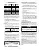
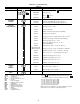
Table 65 — Required User Adjusted Defaults
Table 66 — Motor Overload Settings
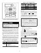
Quick Test —
The test function provides a check on con-
trol inputs and outputs, and can only be conducted when the
unit is in the Standby mode. To put the unit into the Standby
mode, press , then , then . Display will
read STBY YES.
The test function and associated subfunctions should be run
to check all unit inputs and outputs prior to unit start-up. Refer
to the Test Function section on page 96 for additional details on
the test function and performing quick tests.
To operate a test:
1. Enter the desired test subfunction.
2. Press to scroll to the desired test.
3. Press to start the test.
Pressing after a test has started advances the system to
the next test whether the current test has timed out or not. If the
keypad is not used for 10 minutes, the display will return to the
rotating default display. You must press and to
exit quick test. To restart the test procedure, press . To ter-
minate the quick test press ; EXIT TST will be dis-
played. Press and TST CMPL will be displayed, ending
the quick test.
While the unit is in the test function, other functions can be
accessed by pressing the appropriate keys. If a component is
operating under a test function, it will remain operating when
another function (such as temperatures or pressures under the
status function) is accessed. The test function must be reentered
to shut down that component.
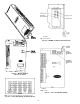
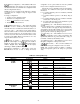
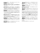
Factory-installed optional VFD is located near the supply
fan and motor. During any service work or programming at
the VFD, operation of the fan and motor is not desirable.
Either disable the supply fan or install the accessory VFD
remote display accessory.
SIZES ITEM
All
Motor overload settings (see Table 66)
054-104
1. Check jumper CC-F
2. GR.UT/bLSF = 1
3. Gr.SF/Sr.n = 1
4. Gr.SF/SrN1 = 0
5. SEtP/tYP = 5 (Save User Settings)
UNIT VOLTAGE
DESIGNATION
AND
IFM HP
DESIGNATION
tHr1
SETTING
Model No.
Position 12
Model No.
Position 15
5
and N 82.0
5
and Q 86.0
6
and A 80.0
6
and K 80.0
IMPORTANT: Be sure unit is in the Standby mode
( ) PRIOR to initiating the test function. The
standby/run mode under MUST read
STBY YES. Test mode will not operate unless unit is
in standby. If the unit is equipped with Remote Start,
place LOCAL/REMOTE switch in the LOCAL (off)
position. The accessory HSIO is required to place unit
control in STBY YES mode and to initiate Quick Test
function.
IMPORTANT: The user MUST press
to re-store the unit software to automatic control. To
return unit to run mode (STBY NO), press
. If the unit is equipped with
Remote Start, place LOCAL/REMOTE switch in
the REMOTE (on) position.
ENTER
ENTER
ENTER
ENTER
ENTER
ENTER
HZ
PERCENT
SECONDS
KW/AMPS/VOLTS
LOCAL/REMOTE
SPEED CTRL
MANUAL/AUTO
RUN MODE
SETUP
PROGRAM
MONITOR
STOP
RESET
READ
WRITE
RUN
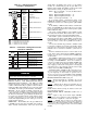
Fig. 50 — Variable Frequency Drive Keypad