
Installation guide


Failure to follow these precautions could result in damage to
the unit being installed:
I. Make all electrical connections in accordance with NEC
ANSI/NFPA Ilatest edition) and local electrical codes
governing such wirthg. In Canada, all electrical connec-
tions must be in accordance with CSA standard C22.1
Canadian Electrical Code P,'u-t I and applicable local
codes. Refer to unit wiring diag,am.
2. Use only copper conductor for connections between
field-supplied electrical disconnect switch and unit. DO
NOT USE ALUMINUM WIRE.
3. Be sure that high-voltage power to unit is within operating
voltage range indicated on unit rating plate. On 3-phase
units, ensure pbases are balanced within 2 percent. Consult
local power company for correction of improper voltage
and/or phase imbalance.
4, Insulate low-voltage wires for highest voltage contained
within conduit when low-voltage control wires are in same
conduit as high-voltage wires.
5. Do not damage internal components when drilling through
any panel to mount electrical hardware, conduit, etc.
r.', LV/_q 2WE_
HIGH-VOLTAGE CONNECTIONS
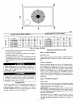
The unit must have a separate electrical service with a field-
supplied, waterproof disconnect switch mounted at, or within sight
from the unit. Refer to the unit rating plate, NEC and local codes
for maximum fuse/circuit breaker size and minimum circuit amps
(ampacity) for wire sizing (See Table 3 for electrical data}.
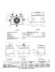
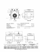
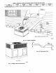
The field-supplied disconnect may be mounted on the unit o_'er the
high-voltage inlet hole (See Figs. 2 and 3).
If the unit has an electric heater, a second disconnect may be
required. Consult the lnstullation, Start-Up, and Service Instruc-
tions provided with the accessory for electrical service connec-
tions.
Operation of unit on improper line voltage constitutes abuse and
may cause unit damage that could affect warranty.
ROUTING POWER LEADS fNTO UNIT
Use only copper wire between disconnect and unit. The high-
voltage leads should be in a conduit until they enter the duct panel;
conduit termination at the duct panel must be watertight. Run the
high-voltage leads through the power entry knockout on the power
entry side panel ISee Fig. 2 and 3 for location and size). When the
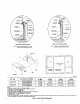
leads are inside the unit. run leads up the high-voltage raceway to
the line wiring splice box (See Fig. 13 through 15). For single-
phase units, connect leads to the black and yellow wires; for
3-phase units, connect the leads to the black, yellow, and blue
wires (See Fig. 18).
CONNECTING GROUND LEAD TO GROUND LUG
Refer to Fig. 18. Connect the ground lead to the chassis using the
ground lug in the wiring splice box.
ROUTING CONTROL POWER WIRES (24-V)
Form a drip-loop with the thermostat leads before routing them
intu the unit. Route the thermostat leads through grommeted,
low-voltage hole provided in unit into unit control power splice
box (See Fig. 2 and 3). Connect thermostat leads to unit control
power leads as shown in Fig. 17.
The unit transformer supplies 24-v power for complete system
including accessory electrical heater. An automatic-reset circuit
breaker (See Fig. 19) is provided in the 24-v circuit; see the caution
label on the transformer or Fig. 20. Transformer is factory wired
lor 230-v operation. If supply voltage is 208-v, rewire transformer
primary, as described in Special Procedures for 208-v Operation
section.
SPECIAL PROCEDURES FOR 208-V OPERATION
I. Be sure unit disconnect switch is open.
2. Disconnect the yellow primary lead /w 110) from the trans-
former. See unit wiring label 1See Fig, 13 and 141.
3. Connect the yellow primary lead (wl i0) to the transformer
terminal labeled 200-v.
Indoor blower-motor speeds may need to be changed for 208-v
operation. Refer to indoor airflow and airflow adjustments section.
PRE-START-UP
10
Failure to observe the following warnings could result in
serious personal injury or death:
1. Follow recognized safety practices and wear protective
goggles when checking or servicing refrigerant system.
2. Do not operate compressor or provide any electric power to
unit unless compressor terminal cover is in place and
secured.
3. Do not remove compressor terminal cover until all electri-
cal sources are disconnected.
4. Relieve and recover all refrigerant from both high- and
low-pressure sides of system before touching or disturbing
anything inside terminal box if refrigerant leak is suspected
around compressor terminals.
5. Never attempt to repair soldered connection while refrig-
erant system is under pressure.
6. Do not use torch to remove any component. System
contains oil and refrigerant under pressure.
To remove a component, wear protective goggles and
proceed as follows:
a. Shut off electrical power to unit.
b. Relieve and reclaim all refrigerant from system using
both high- and low-pressure ports.
c. Cut component connecting tubing with tubing cutter and
remove component from unit.
d. Carefully unsweat remaining tubing stubs when neces-
sary. Oil can ignite when exposed to torch flame.
Use the Start-Up Checklist supplied at the end of this book and
proceed as follows to inspect and prepare the unit for initial
start-up:
1. Remove all access panels.
2. Read and follow instructions on all DANGER, WARNING,
CAUTION, and INFORMATION labels attached to, or
shipped with, unit.
3. Make the following inspections:
a. Inspect for shipping and handling damages such as broken
lines, loose parts, disconnected wires, etc.
b. Inspect for oil at all refrigerant tubing connections and on
unit base. Detecting oil generally indicates a refrigerant
leak. Leak-test all refrigerant tubing connections using
electronic leak detector, or liquid-soap solution. If a refrig-
erant leak is detected, see following Check for Refrigerant
Leaks section.
c, Inspect all field and factory-wiring connections. Be sure
that connections are completed and tight.
d. Inspect coil fins. If damaged during shipping and handling,
carefully straighten fins with a fin comb.
4. Verify the following conditions: