
Installation guide


B
3
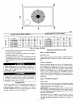
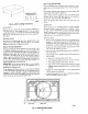
MAXIMUM ALLOWABLE
DIFFERENCE (in.)
/
A-B B-C / A-C
t/4 1/4 1/4
Fig. 6---Unit Leveling Tolerances
C99065
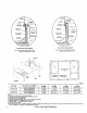
SLAB MOUNT
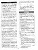
Place the unit on a solid, level concrete pad that is a minimum of
4 in. thick with 2 in. above grade (See Fig. 71. The slab should
extend approximately 2 in. beyond the casing on all 4 sides of the
unit. Do not secure the unit to the slab except when required by
local codes.
GROUND MOUNT
The unit may be installed either on a slab or placed directly on the
ground if local codes permit. Place the unit on level ground
prepared with gravel for condensate discharge.
Step 3_Provide Clearances
The required minimum service clearances are shown in Figs. 2 and
3. Adequate ventilation and outdoor air must be provided. The
outdoor fan draws air through the outdoor coil and discharges it
through the top fan grill. Be sure that the fan discharge does not
recirculate to the outdoor coil. Do not locate the unit in either a
comer or under an overhead obstruction. The minimum clearance
under a partial overhang (such _s a normal house overhang! is 48
in. above the unit top. The maximum horizontal extension of a
partial overhang must not exceed 48 in.
IMPORTANT: Do not restrict outdoor airflow. An air restriction
at either the outdoor-air inlet or the fan discharge may be
detrimental to compressor life.
Do not place the unit where water, ice, or snow from an overhang
or roof will damage or flood the unit. Do not install the unit on
carpeting or other combustible materials. Slab-mounted units
should be at least 4 in. above the highest expected water and runoff
levels. Do not use unit if it has been under water.
Step 4_Rig and Place Unit
Rigging and handling of this equipment can be hazardous for many
reasons due to the installation location (roofs. elevated structures.
etc. /
Only trained, qualified crane operators and ground support staff
should handle and install this equipment.
When working with this equipment, obserxe precautions in the
literature, on tags, stickers, and labels attached to the equipment,
and any other salety precautions that might apply.
Follow all applicable safety codes. Wear safety shoes and work
gloves.
INSPECTION
prior to initial use, and at monthly intervals, all rigging brackets
and straps should be visually inspected for any d_nage, evidence
of wear, structural deformation, or cracks, particular attention
should be paid to excessive wear at hoist hooking points and load
support areas. Brackets or straps showing an) kind of wear in these
areas must not be used and should be discarded.
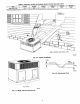
INSTALLATION
I. Remove unit from shipping carton. Leave top shipping skid on
the unit as a spreader bar to prevent the rigging straps from
damaging the unit. If the wood skid is not available, use a
spreader bar of sufficient length to protect unit from damage.
2. Position the lifting bracket assembly around the base of the
unit. Be sure thestrap does not twist.
3. Place each of the 4 metal lifting brackets into the handholds in
the composite pan.
4. Thread lifting bracket strapping around bot/om perimeter of
unit 0s follows:
a. Open lever of tension buckle (ratchet type).
b. Feed strapping through tension buckle as shown in Fig. 8.
c. Pull strapping through tension buckle unit taut.
d. Snap lever down to lock strap in tension buckle. To release
strapping, squeeze safety latch, lift lever, and pull webbing
outward.
5. Tighten the tension buckle until it is taut. Lifting brackets
must be secure in the handholds.
6, Attach field-supplied clevis or hook of sufficient strength to
hole in the lifting bracket (See Fig. 91.
2-
EVAI_ COIL COND. COIL
Fig. 7--Slab Mounting Detail
6
C90096