
Installation guide

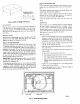


HOOK
J
J
FEED
C99067
Fig. 8---Threading Belt
914-137"
136"-54")
D_TAIL A
SCALE0 250
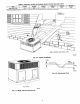
tIGHTEN STRAPPING SECURELY
WfTH TENSION BUCKLE
INSTALL SAFE I_" _TRAPS TO
RIGGING CLEVI_ AT 4 RIGGING BRACKET_
PLACE RIGGING BRACKET A_SEMBLY IN 4
HANO HOLES AND INSTALL TIE DOWN STRAP
ARODND PERIMETER OF UNIT AND THROUGH
SPACE IN BRACKET ASSEMBLy
C99075
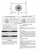
UNIT MAXIMUM WEIGHT A B
Size lb. kg in. mm. in, mm.
50JZ024 321 145.6 19.0 482.6 18.25 463.6
50JZ030 342 155.2 20.0 508 19,25 489
50JZ036 I 350 158.8 20.0 508 19.0 482.6
80JZ042 372 168,8 21.0 533.4 20.5 520.7
50JZ048 377 171.0 20.0 508 21.25 539.8
50JZ060 450 204.2 21.0 533.4 20.0 508.0
Fig. 9--Suggested Rigging
7. Attach the 2 safety straps directly to the clevis or hook at the
4 rigging brackets. DO NOT attach the safety straps to the
lifting brackets (See Fig. 9}.
8. Position lifting point directly over the tmit's center of _avity.
9. Lift unit. When unit is directly over the roof curb. remove the
2 safety straps. Lower the equipment onto the roof curb.
10. After the unit is placed on the roofcurb or mounting pad,
remove [he top crating. On 50JZ060 units only, 2 wire ties
fastened to the outdoor coils and reversing valve/accumulator
assembly must be cut. Remove the left and front louver panels
and corner post to access wire ties. The wire tie to he cut on
the left is located approximately 4" down the tube sheet. The
wire tie to be cut on the right is located approximately 6"
down the tube sheet.
Step 5--Select and Install Ductwork
The design and installation of the duct system must be in
accordance with the standards of the NFPA for installation of
7
non-residence type air conditioning and ventilating systems, NFPA
9flA or residence type. NFPA 90B and/or local codes and ordi
nantes.
Select and size ductwork, supply-air registers, and return air grilles
according to ASHRAE (Amefican Society of Heating, Refrigera
tion, and Air Conditioning Engineers) recommendations.
The unit has duct flanges on the supply and return-air openings on
the side of the unit.
When designing and installing ductwork, consider the following:
For vertical supply and return units, tools or parts could drop
into ductwork and cause serious injury or death. Install a 90
de_ee turn in the return ductwork between the unit and the
conditioned space. If a 90 degree elbow cannot be installed.
then a grille of sufficient strength and density should be
installed to prevent objects from falling into the conditioned
space. Units with electric heaters require 90 degree elbow in
supply duct.
I. All units should have field-supplied filters or accessory filter
rack installed in the return-air side of the unit. Recommended
sizes for filters are shown in Table 1.
2. Avoid abrupt duct size increases and reductions. Abrupt
change in duct size adversely affects air perforroance.
IMPORTANT: Use flexible connectors between ductwork and
unit to prevent transmission of vibration. Use suitable gaskets Io
ensure weather tight and airtight seal. When electric heat is
installed, use fireproof canvas (or similar heat resistant material)
connector between ductwork and unit discharge connection. If
flexible duct is used, insert a sheet metal sleeve inside duct. Heat
resistant duct connector (or sheet metal sleeve) must extend 24-in.
from electric heater element.
3. Size ductwork for cooling air quantity (cfm). The minimum
air quantity for proper electric heater operation is listed in
Table 2. Heater limit switches may trip at air quantities below
those recommended.
4. Seal. insulate, and weatherproof all external ductwork. Seal,
insulate and cover with a vapor barrier all ductwork passing
through conditioned spaces. Follow latest Sheet Metal and Air
Conditioning Contractors National Association (SMACNA)
and Air Conditioning Contractors Association (ACCA) mini-
mum installation standards for residential heating and air
conditioning system_.
5. Secure all ducts to building structure. Flash, weatherprooL and
vibration-isolate duct openings in wail or roof according to
good construction practices.
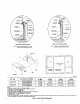
CONVERTING HORIZONTAL DISCHARGE UNITS TO
DOWNFLOW (VERTICAL) DISCHARGE UNITS
serious injury or death.
1. Open all electrical disconnects before starting any service
work.
2. Remove horizontal duct covers to access bottom return and
supply knock out panels.
3. Use a screwdriver and hammer to remove the panels in the
bottom of the bzL_e pan.