
Installation guide

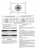
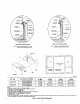
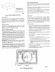


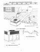

Table 1--Physical Data--Unit 50JZ
UNIT SIZE
NOMINAL CAPACITY (ton)
OPERATING WEIGHT (lb.)
COMPRESSOR QUANTITY
TYPE
REFRIGERANT
REFRIGERANT METERING DEVICE
Refrigerant (R-410A) Quantity (lb.)
ORIFICE ID (in.)
ORIFICE OD (in,)
OUTDOOR COIL
Rows.,. Fins/in.
face area (sq. ft.)
OUTDOOR FAN
Nominal Airflow (CFM)
Diameter
Motor HP (RPM)
INDOOR COIL
Rows._ Fins/in.
face area (sq. ft.)
INDOOR SLOWER
Nominal Airflow (CFM_
Size (in,)
Motor (HP)
HIGH-PRESSURE SWITCH (psig)
Cutout
Reset (Auto)
LOSS-OF-CHARGE/LOW-PRESSURE SWITCH
(Liquid Line) (psig)
Cutout
Reset (Auto)
RETURN-AIR FILTERS (in._"
throwaway
50JZ024 I 50JZ030 50JZ036 50JZ042 50JZ048 I 50JZ060
2 I 2-1/2 3 3-1/2 4 I 5299 320 328 350 355 428
1
SCROLL COMPRESSOR
R-410A
Accurater
7.0 8.9 9.3 9.5 10,6 12.4
0.061 0.061 0.067 0.073 0.076 0.088
0.032 (2) 0.040 (2) 0.040 (2) 0.038 (2) 0.046 (2) 0.052 (2)
2...17 2...17 2...17 2...J7 2..._7 2...17
8.5 10.3 10.3 13.5 13.5 15.4
2350 2350 2800 2500 3300 3300
22 22 22 22 22 22
1/8 (825) 1/8 (825) 1/4 (1100) 1/8 (825) 1/4 (1100) 1/4 (1100)
3...15 3...15 4...15 3...15 4...15 4,..15
3.7 3.7 3.7 4.7 4.7 / 5.7
800 1000 1200 1400 1600 / 1750
10x10 10x10 10x10 11x10 11x10 11x10
1/4 1/4 1/2 1/2 1/2 1
610 ± 15
420 ± 25
20± 5
45± 10
20x20x1f20x20Xli 20x2,xlf 24x30 1f 24x30Xlf 2,x30x1
• Required tilter sizes shown are based on the larger of the ARI (Air Conditioning and Refrigeration Institute) rated cooling airflow or the heating airflow velocity of 300
if/minute for throwaway type or 450 if/minute for high-capacity type. Air tilter pressure drop for non-standard filters must not exceed 0.08 in. wg.
NOTE: These panels are held in place with tabs similar to an
electrical knockout.
4. Reinstall the horizontal duct covers (Fig, 11) to block off the
horizontal air openings.
NOTE: Avoid abrupt duct size increases anti reductions. Abrupt
change in duct size adversely affects air performance.
r_ 'kk_r:_ttLllT[d
Step 6--Provide for Condensate Disposal
NOTE: Ensure that condensate-water disposal methods comply
with local codes, restrictions, and practices.
The 50JZ units dispose of condensate through a 3/4 in. NPT female
fitting that exits on the compressor end of the unit. Condensate
water can be drained directly onto the roof in rooftop installations
(where permitted) or onto a gravel apron in ground level installa-
tions, Install a field-supplied condensate trap at end of condensate
connection to ensure proper drainage. Make sure that the outlet of
the trap is at least I in. lower than the drain-pan condensate
connection to prevent the pan from overflowing. Prime the trap
with water. When using a gravel apron, make sure it slopes away
from the unit.
If the installation requires draining the condensate water away
from the unit, install a field-supplied 2 -in. trap at the condensate
connection to ensure proper drainage. Conden,_ate trap is available
as an accessory or is field supplied. Make sure that the outlet of the
trap is at least I in. lower than the unit drain-pan condensate
connection to prevent the pan from overflowing. Connect a drain
trough using a minimum of field-supplied 3/4 -in. PVC or
field-gupplJed 314 .in. copper pil)_ _ outh_l elt_ of _ 2 -in.
(See Fig. 12). Do not undersize the tube. Pitch the drain trough
downward at a slope of at least 1 in. every, 10 ft. of horizontal run.
Be sure to check the drain trough for leaks. Prime the trap at the
beginning of the cooling season start-up.
Step 7_nstall Electrical Connections
The unit cabinet must have an uninterrupted, unbroken
electrical ground to minimize the possibility of personal
injury if an electrical fault should occur. This ground may
consist of an electrical wire connected to the unit ground lug
in tile _ontrol compartment, or conduit approved for electrica_
ground when installed in accordance with NEC, ANSI/NFPA
American National Standards Institute/National Fire Protec-
tion Association (latest edition) iin Canada, Canadian Elec-
trical Code CSA C22.1) and local electrical codes. Failure to
adhere to this warning could result in serious injury or death.