® Irn to the Expertg Controls, Start-Up, Operation, Troubleshooting TABLE GENERAL Instructions OF CONTENTS SAFETY CONSIDERATIONS ......................... ......................................... BASIC CONTROL USAGE Page 2 3 ........................... Service and Alarm Output ..................................... 11 Economizer Monitoring ............................. 11 Economizer Damper Control ......................... 11 CONTROLS OPERATION ...........................
Variable Frequency Drive (VFD) ...................... 53 Recognize Integrated Gas Control (IGC) Board 54 When you see this symbol on the unit and in instructions manuals, be alert to the potential for personal iniury. ................... Low Voltage Terminal Strip (TBI) ..................... 55 Scrolling Marquee Display 56 Accessory Navigator TM .......................... Display ....................... 56 Carrier Comfort Network (CCN)® Interface .............
• Service Test GENERAL This publication contains and Troubleshooting Start-Up, Controls, information Operation, for the 48/50PD Service, rooftop units. (See Table 1.) These units are equipped with ComfortLink "_ controls version I.X or higher and use Puron ® refrigerant. The specific base unit installation instructions and/or wiring label diagram may also be required in conjunction with this book as a guide to a specific unit on the roof.
downarrowkeysto scroll through the top-level categories. These economizer commanded position (EC.CP) is forced, the Navigator display shows "80F', where the "F' is blinking to signify a force on the point. The Scrolling Marquee display shows "80." Where the are listed in Appendix A and will be indicated on the Scrolling Marquee by the LED next to each mode listed on the face of the display. When a specific mode or sub-mode is located, push .... is blinking to signify a force on the point.
/1 Conventions Used in This Manual The following conventions for discussing the local display (Scrolling be used in this manual. Marquee configuration or Navigator points T, accessory) for will Point names will be written with the Mode name first, then any submodes, then the point name, each separated by an arrow symbol (-+). Names will also be shown in bold and italics. As an example, the Fan Status Switch which is located in the Configuration mode, and Unit sub-mode UNIT-+ FN.S W.
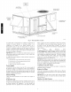
CONTROL BOX AND COMPRESSOR \ ELECTRICAL OPTIONS \ \ PANEL \ \ \ \"\ OUTDOOR \ INDOOR MOTOR \ \ ACCESS \ J DOOR f AIR SCREEN (HIDDEN) \\ \ \ CONDENSER COIL ACCESS PANEL \ GAS SECTION ACCESS / BASEPAN / FILTER ACCESS DOOR CONNECTIONS ACCESS PANEL C 07002 Fig. 4 - Panel and Filter On 3-phase units, it is important to be certain the compressors are rotating in the proper direction.
Accessory Installation CONTROLS Check to make sure that all accessories including sensors have been installed and wired as required by the instructions and unit wiring diagrams. The following Orifice factory-installed options. configuration at start-up. Change This unit is factory gas at an elevation (48PD Only) assembled for heating from sea level to 2000 operation Use accessory high altitude kit when installing elevation of 2000 to 7000 ft.
Table 3 1 ITEM EXPANSION Application Specific Configurations DEFAULT UNITS Air Setpoint DISPLACEMENT VENTILATION SINGLE ZONE VAV SASP Cool Supply 65 dF 65 55 FS.MX Supply Fan Maximum Speed 100 % 100 100 FS.MN Supply Fan Maximum Speed 20 % 20 70 FS.VM Vent Mode Fan Speed 50 ^F 50 50 M IN.C M in Corn pressor Capacity 70 % 15 70 3 FS.CD Fan Speed Control SA.MU SASP Maximum Reset Up SA.MD SASP Maximum Reset Down MRMX Econ Min at Max Fanspeed PE1 .
Fan Status Filter If a Fan Status accessory was field installed, the unit must configured for it by setting Configuration---_UNIT---_FN.SW normally preferred open (1) or normally configuration. IMPORTANT: Fan Status. Fan Status closed input Table DISPLAY MENU TIMECLOCK SCH.L SUBr-] r-]SUB MODE (2). Normally open (1) is the is not on the ternfinals 4 -- Setting KEYPAD ENTRY ENTER Time DISPLAY ENTER PER.
Programming Operating The _ ComfortLink different assigned controls schedules (Periods to the desired days SERVICE Schedules will accommodate up to eight 1 through 8), and each schedule is of the week. Each schedule includes The Service Test function compressors, exhaust fans, Use of Service would set days Monday through Friday to ON for Period 1. Then the user would configure the Period 1 Occupied From point to 08:00 and the Period 1 Occupied To point to 17:00.
Cooling Fire Shutdown Test The cooling (COOL) submenu is used to change output status for testing the cooling function. The fans (FANS) and heating (HEAT) service test outputs are reset to OFF for the cooling service test. The digital scroll controller power test (CTLR) turns on and off the compressor controller. The compressor capacity test (CPAC) is used to run the compressor at a desired capacity of 15% to 100%. If a capacity is chosen between 1 and 14, the capacity will be set to 15%.
Password Enable (PROT) This variable password is configurations. Service (PSWD) is the 4-digit if a demand LEDs unit only password that is required if (TEST) limit has been placed on the unit's Displays if one or more refrigerant circuits operation of the ComfortLink "_ display.
RH Sensor On OAQ Input Level 1 Priority (RH.S) This configuration identifies if a space relative humidity sensor is installed on the outdoor air quality (OAQ) input. A YES value enables SP.RH display, A NO value disables SP, RH display and use. Space Humidity Switch (RH.SW) This configuration identifies if a space relative humidity switch is installed on the ENTHALPY input, and what status (normally open, normally LOW.
(Configuration--+CCN--+SCH.O--+OV.SP) The length Timed of the override Override (Con figuration--+CCN--+ Compressor period SCH.O--+O is set to YES. is detemfined Hours by the setting V>EX). duct static pressure difference and indoor fan RPM. Make correction to static pressure for all options installed in the unit per the accessory pressure drop table.
Outdoor When Fan Operation The 48/50 PD units use a multi-speed outdoor fan motor to control the head pressure within an acceptable range at low outdoor ambient temperatures. On the 48 and 50 PD-05 and 06 size units the outdoor compressor The outdoor fan contactor is powered on the load side of the contactor so the outdoor fans will run only when the compressor contactor is contactor is not energized energized. the outdoor FAN LEVEL When the outdoor fan fan runs at high speed.
a.(Configuration--,ECON--,UEFC = O) - Disabled (Configuration--+ECON--+MP.MX) unoccupied Cooling occupied setpoints. space temperature nmst be higher then the nfid-point between the occupied cooling and heating set points. only occur when the time until the next occupied period is less than the Free Cool PreOcc nfinutes. in 2. Free Cool Time (FC.TM) PreOcc Time (C onfiguratio n--_ E CON--_ F C. TM) FC.
exceed Econ Min at Max (Configuration--_ECON--_MP_X) (Configuration--,AIR.Q--,OVRdP) Fan Speed or IAQ Override Position to provide econonfizer Fan cooling. IA.CF = 3 (Control Minimum Position) When IA.CF = 3, an external 4 to 20 mA source is used to set the minimum position. The 4mA signal corresponds to 0% and the 20 mA signal corresponds to 100%. In this mode, configuration such as Econ Min at Max Fan Speed (Configuration--,ECON--,MP.MX), Econo Min IAQ Position (Configuration--,AIR.Q--,AQ.
variable orUnoccupied CoolSetPoint(Setpoints--->UCSP) the Fan Speed (Configuration--->COOL--->FS.CD) Control configuration plus Demand variable the indoor fan will run at 100%. When the temperature in the conditioned space is between the Occupied Cool Set Point (Setpoints--->OCSP) and Occupied Cool Set Point (Setpoints--->OCSP) plus the (Configuration--->COOL--->FS.CD) indoor fan modulates (Setpoints-,OCSP) (Setpoints-,UCSP).
Forall units with Economizers: pressure 1. 1.The outdoor temperature is below the Econo Cool Hi Temp Limit (Configuration--_ECON--_EH_LO) and above the Econo Cool Lo Temp Linfit (C onfiguration--+ readings to deternfine the actual Indoor Fan Max Speed CFM (Configuration--+ECON--+IDF.C). Economizer Position % E CON--+ EL_LO) . MAX P For units with Enthalpy 2. 1.The outdoor is below Control enthalpy is low and the outdoor temperature the Econo Cool Hi Temp Limit (Configuration--+ECON--+EH.
Quality (IAQ) section of the Econonfizer Operation section above for more details on Demand Control Ventilation (DCV). Economizer Operation for Units Equipped with Return Air COy Sensor Only When the CO 2 sensor detects a CO 2 level or IAQ Level (Inputs--+AIR.O--+IAO) below the AQ Differential Low (Configuration--,AIR.O--,AOD.L) value the MP.25, MP.50, MP.75 and MP.MX points will be recalculated to new values for MP.25, MP.50, MP.75 based on the Econ Min IAQ Position (Configuration--,AIR.O--,AO.MN).
beextended by 15seconds. Then_axinmm delayis 3 Once modified by the IGC, to the configured minutes. the fan off delay will not change Fan-off Delay, Gas (Configuration--,HEAT--,FOD.G) control. unless power is reset back Heat to the A light emitting diode (LED) is provided on the IGC to indicate status. During normal operation the LED is continuously on. See the Troubleshooting section if the LED is off or flashing. The IGC is located behind the gas section access panel door.
willnotbeinterrupted totheburners andheating willcontinue. Oncemodified, thefanondelaywill notchange backto 45 seconds unless power isreset tothecontrol. When theindoor fan turns onafter the40or45second delay theindoor fanwillrunat 100% fanspeed. Supply-Air Temperature Sensor (SAT) The SAT Heat (Configuration--,HEAT--,SAT--,SATart) Temperature (Temperatures-,AIR.T-,SAT) Mode Sensing affects the Supply Air value displayed.
Temperature Compensated Start Logic The following conditions • Unit is in unoccupied • Next occupied • Current CCN Broadcast nmst be met for the algorithm state. time is valid. Schedule time of day is valid. • Valid space temperature reading is available (sensor Acknowledger (BROD-->B.ACK) If this configuration is set to ON, then when any broadcasting is done on the bus, this device will respond to and acknowledge. Only one device per bus can be configured for this option.
Loadshed Group Number before (S.GRP) This corresponds to the loadshed supervisory devices that reside elsewhere on the CCN network and broadcast loadshed and redline commands to its associated equipment parts. This variable will default to zero which is an invalid group number. This allows the loadshed flmction to be disabled until configured. Redline Max Capacity This configuration cooling/dehunfidification loadshed condition.
AUXIis notblinking, checktheDIPswitch positions onthe board, If theredLEDsarenotblinkingin unison, verifythat correct power is beingsupplied toallmodules, A blinking red LEDattherateofoncepersecond means thatsoftware is not loaded ontheboard, Also,besure thattheboard issupplied with thecurrent software, If necessary, reload current software, Aboard LEDthatislit continuously should bereplaced, Green LED The MBB, Equipment whenever power is on, If LEN LED is not blinking, check LEN connections for potentia
only the outdoor temperature to control the outdoor fans. If both the SCT and OAT fail, then circuit shutdown alarm will occur also. The cause of the alert is usually a faulty thernfistor, a shorted or open thernfistor caused by a wiring error, or a loose connection. Alert Code T066 - Circuit A Saturated Suction Temperature Thermistor Failure This alert occurs when the unit's suction transducers are turned off internally. Cooling will not operate.
Recovery is automatic but MBB board replacement may be necessary. Cycling the power to the control should be tried before board replacement. found Alarm Code T155 - Serial EEPROM Alert Code Storage Failure Error at variable Configuration-+UNIT-+FS.SW. Verify that the configuration is set correct, verify the wiring This alarm resets automatically. T408 and auxiliary device. - Dirty Air Filter Configuration data in the serial EEPROM chip can not be verified.
Initiate economizer using the Service calibration (Service Test--,INDP--, Test menu. The economizer procedure will try to find new maximum positions. If the alert does not clear automatically calibration procedure economizer rotation. is complete, clamp.
Table 8 -ALARM OR ALERT NUMBER DESCRIPTION Digital Compressor Compressor T051 A1 Safety Trip Service Test - Compressor A1 Safety Trip T066 Circuit A Saturated Condensing Temp Thermistor Failure Circuit A Saturated Suction Temperature Thermistor Failure T073 Outdoor Air Temperature T074 Space Temperature T075 Supply Air Temperature T076 Return Air Thermistor T077 Space Relative Humidity Sensor Failure T092 Circuit A Suction Pressure Transducer Failure Thermistor Thermistor Thermistor F
Table 8 -ALARM OR ALERT NUMBER DESCRIPTION ComfortLink T_Alarm Codes ACTION TAKEN BY CONTROL RESET METHOD (cont) PROBABLE CAUSE T178 Loss of Communication Control Board with the Capacity Unit shutdown -HVAC disable Automatic Communication wiring problem with AUX1 or faulty MBB, ECB, or AUXl T179 with the Economizer Communication wiring problem with ECB or faulty MBB, ECB, or AUXl Automatic A200 A404 T408 Linkage Timeout Fire Shutdown Dirty Filter No economizer operation No economizer o
Table 9-- Cooling Service PROBLEM Compressor Analysis CAUSE REMEDY Power failure. and Fan Will Not Start Fuse blown CB2. or circuit Disconnect off. Compressor breaker tripped. Check CB1 and set point or supply Outdoor too low. temperature Check time guards using ComfortLink_' Marquee also the DSC has a 2 minute set point not Check cooling Marquee. Insufficient line voltage. Active alarm. Compressor Continuously. Unit undersized for load. charge. Recover 2.
measured atemperature above 268F(131C)orthethermistor has the system controller providing the signal may not be powered. short circuited (jumpered out). The DSC will de-energize the compressor contactor and unloader TheDSCwillde-energize thecompressor contactor andunloader solenoid and the alarm relay contacts will close causing a T051 solenoid, andthealarm relaycontacts will close causing aT051 alert on the ComfortLink Control. Once the system controller demand signal input has risen above 0.
Economizer Use the unit the economizer display Scrolling Verify codes cleared, operation Service Test of and steps Scrolling Marquee correct how display, Test to See (See Table installed section test the 11 and 11.) site using the Table 5). The using the general using the Serviee 2. Enter needed TEST and turn ON test mode, A in order to turn ON the Service password 3.
Heating Use the the unit heating Scrolling status Appendix A) Marquee display for display and the information current alarms correct any causes. configurations per alarms Phase Troubleshooting and conditions on alarm history (See Table installed are corrected stages and indoor mode. (See Table fan may be heating for any heating Verify the codes and control accessories.
I FLASH _O_FED - INDOOR (HEATING) FAN [_ELAY 2 _S - OF_-NN SW_rCH 3 _ - _ iNE_J_TES FLAME CLOSED GAS OF UME ] FF- SFJV_OR WffH VALVE 4 FL_..S - L_IT SWITCH CYCLED 4 _MES ON CALL FK)R HEAT t-HEATING .
Table LED FLASH CODE ACTION TAKEN CONTROL DESCRIPTION On Normal Off Hardware 1 Flash 13 -- Operation IGC Board BY LED RESET Codes METHOD __ Failure Alarm PROBABLE __ No gas heating. __ -- Loss of power to the IGC. Check 5 amp fuse on IGC, power to unit, 24V circuit breaker, transformer, and wiring to the IGC. High temperature limit switch opens during heat exchanger warm-up period before fan-on delay expires.
Thermistor Troubleshooting The electronic control uses thermistors to sense temperatures used to control operation of the unit. Resistances at various temperatures are listed in Table 15-17. Thermistor pin connection points are shown in the Maior System Components section. The general locations of the thermistors are shown the Maior System Components section. Air Temperatures Air temperatures are measured with 10 kilo-ohm thermistors.
Sensor Trim Corrective offsets can be applied to the space temperature and the supply air temperature sensor readings. These corrections are set in the Configuration--,TRIM menu for the display, or in the Maintenance--,TRIM section for available table for CCN. See the Indoor Air Quality adjustments to IAQ and OAQ sensor readings. The space temperature calibration temperature may value be corrected by entering either a in SPT.C, or an offset temperature value in SPT.T.
Table 15 -- Temperature RAT, TEMP (F) -25 -24 -23 -22 -21 -20 -19 -18 -17 -16 -15 -14 -13 -12 -11 -10 -9 -8 -7 -6 -5 -4 -3 -2 -I 0 I 2 3 4 5 6 7 8 9 I0 11 12 13 14 15 16 17 18 19 20 21 22 23 24 25 26 27 28 29 30 31 32 33 34 35 36 37 38 39 40 41 42 43 44 45 46 47 48 49 5O 51 52 53 54 55 56 57 58 59 6O VOLTAGE DROP (V) 4.758 4.750 4.741 4.733 4.724 4.715 4.705 4.696 4.686 4.676 4.665 4.655 4.644 4.633 4.621 4.609 4.597 4.585 4.572 4.560 4.546 4.533 4.519 4.505 4.490 4.476 4.461 4.445 4.429 4.413 4.397 4.
TEMP (F) -25 -24 -23 -22 -21 -20 -19 -18 -17 -16 -15 -14 -13 -12 -11 -10 -9 -8 -7 -6 -5 -4 -3 -2 -1 0 1 2 3 4 5 6 7 8 9 10 11 12 13 14 15 16 17 18 19 20 21 22 23 24 25 26 27 28 29 30 31 32 33 34 35 36 37 38 39 40 41 42 43 44 45 46 47 48 49 50 51 52 53 54 55 56 57 58 Table 16 -- Temperature VOLTAGE DROP (V) 3.699 3.689 3.679 3.668 3.658 3.647 3.636 3.624 3.613 3.601 3.588 3.576 3.563 3.550 3.536 3.523 3.509 3.494 3.480 3.465 3.450 3.434 3.418 3.402 3.386 3.369 3.352 3.335 3.317 3.299 3.281 3.262 3.243 3.
Table 17 -- Temperature vs Resistance Values for the DTT Thermistor (86K at 25 °C Resistors) Degree C Degree F Resistance (k Ohms) - 40 - 40 2889.60 - 65 - 61 2087.22 - 30 -25 - 20 - 15 - 22 -16 - 4 5 23 363.99 10 15 20 25 50 59 68 77 55 60 65 161 140 149 10.79 85 185 9.20 90 194 7.87 95 206 6.77 1 O0 212 5.85 105 221 5.09 110 260 4.45 115 269 3.87 120 248 3.65 125 257 2.92 130 266 2.58 165 275 2.28 140 284 2.02 145 296 1.80 150 602 1.
Table PRESSURE (psig) 0 2 VOLTAGE DROP (V) 0.465 18 -- Pressure (psig) vs. Voltage PRESSURE (psig) 68 Drop Values for Suction Pressure Transducers VOLTAGE DROP (V) 1.135 PRESSURE (psig) 136 VOLTAGE DROP (V) 1.804 PRESSURE 204 2.474 1.824 206 2.493 208 2.513 210 2.533 (psig) VOLTAGE DROP 4 0.485 0.505 70 72 1.154 1.174 138 140 6 0.524 74 1.194 142 1.844 1.863 8 0.544 0.564 76 78 1.214 1.233 144 146 1.883 1.903 212 2.553 214 2.572 80 82 1.253 1.273 148 150 1.
R C (ECB) J2 J1 T_AN2 01 J [ 48HG503976 I 4.0 C08582 Fig.
1 POWER EXHAUST J FlOP/ACCESSORY TBI Jll 4 LSa TRA_I 81 Jll 2 B J10 19} _k<_ I_ _ r..................................... _i:;_-, .Fi.L.; 111........ _-, _ 2'"_,'?_ '_'_ ÷ I ........................................................ RED ) T TO MBf_J7 9 v ................ ............ GRY BL_..... BL}{ ............... L_RN-- -G>> CO.TRO. ................. YEL L _ SWITCHES 4. 5 AND 70_ GRNI _ QUIP [ G_D 4.8HG503977 4.0 C08583 Fig.
1 : NACR ] D SCON ECTI S[D _ ,SEE ncn. / v i " BLNI _ / " I_ _y KE2_YE[ : :FLOP _PHASE L_S ]_OTECTI_ U., ...................... ..... ............................... / I ',i _K _ D_K " / ........... I . _f3U I / ; / Y[!I ; I CCHR t / _ {_) ......................... I1 .................................................................................................................................................... B U IFC _ ..--J _ \I RANI vLVL}Kl ......................
D]:T AND UC LOCAIION RAT UNIT CONTROL BOX TRAN 1 i ...... : _ // TRAN 2 _"i¸ Z{: CO MPRESSOR [ 7 -_ CONTACTO ECB ...... CURRENT SENSOR AUXI DSC (:08657 Fig.
Main Base Board (MBB) See Fig. 16 and Table 19. The MBB is the center of the ComfortLink control system. It contains the maior portion of the operating software and controls the operation of the unit. The MBB continuously monitors input/output channel information received from its inputs and from the Economizer Control Board (ECB). The MBB The MBB and other receives also receives discrete or inputs from thermistors the Current digital Sensor inputs inputs.
Table 19-- MBBConnections DISPLAY NAME POINT DESCRIPTION SENSOR LOCATION TYPE OF I/O CONNECTION PIN NUMBER INPUTS Input power from TRAN1 control box 24 VAC J1, 1-3 IGC Fan Request gas section switch input J6, 4 switch input J6, 6 switch input switch input J7, 4 J7, 6 FDWN Fire shutdown switch HUM Space Humidity switch Digital Scroll Unloader C.ALM Scroll Compressor CMRA Compressor Alarm switch input J7, 8 switch input J7, 10 FIL.
Economizer The ECB controls Control Board the economizer By (ECB) actuator. (See Fig. 17 and Table 20.) The control signal from the ECB uses either the MFT (Multi-Function Technology) digital communication protocol or a 4 to 20 mA output signal as defined by the configuration Configuration--_ECON--_E.CTL. The ECB has inputs for Indoor Air Quality (IAQ), Outdoor Air Quality (OAQ), enthalpy and RH sensor. It also controls two power exhaust outputs.
Table 20 -DISPLAY NAME ECB Connections POINT DESCRIPTION SENSOR LOCATION TYPE OF I/O CONNECTION PIN NUMBER INPUTS Input power from MBB control box 24 VAC J1, 1-2 field installed switch input J4, 2 economizer, or return/space switch input J4, 4 Indoor air quality sensor return/space 0-20 mA J5, 2 Outdoor air quality sensor, or Relative humidity sensor field installed 0-20 mA J5, 5 Ground Ground J5, 3 J7, 3 Output power to enthalpy switch 24 VAC J4, 3 Output power for loop power s
Modulation The AUXI Board board controls for the ECB, communicate. (AUX1) the compressor capacity and the indoor fan speed (See Fig. 18 and Table 21.) It outputs a l-5vdc and a 2-10vdc signal to the DSC and VFD for capacity and fan speed, respectively. This board is also used as the LEN connection therefore IMPORTANT: (SI) The AUXI that is factory be in the off position buss must be board operational has an 8-position set for its LEN address.
Digital Scroll Control The DSC board controls and Table 22.) It receives determined by the cooling Board The (DSC) the compressor's capacity. a l-5vdc algorithm. from the AUX1 signal (See DSC solenoid Fig. 19 has direct unloader control of the R a specific and pulses capacity. D4 D2 T6 T4 T2 P6 P4 P2 C4 C2 24 24 D3D1 T5T3T1 P5P3Pl C3C1 VACCOM .,i {]_ See the troubleshooting Power LED (Green) .... CC TI C Unloader LED T2 Alert LED (Red) (08659 Fig.
Variable Frequency The VFD varies Drive (VFD) the frequency of the AC voltage supplied to the indoor fan. (See Fig. 20 and Table 23.) This causes the variance in the speed of the fan. The commanded fan speed is received by the VFD from the AUXI board as a 2-10vdc .... signal. The AII DIP switch must be in the off (or towards "U") position to properly read the analog signal. There are three jumper wires that must remain installed for proper operation.
Integrated Gas Control (IGC) Board The IGC is equipped with an LED (light-emitting diode) for diagnostics. See the Troubleshooting section for more information. The IGC is provided on gas heat units. (See Fig. 21 and Table 24.) The IGC controls the direct spark ignition system and monitors the rollout switch, limit switch, and induced-draft motor Hall Effect switch. RED LED-STATUS LH33WPOO2A II 1068-12 II II ( 07028 Fig.
Low Voltage Terminal Strip Fig. 22 and Table 25.) The circuit breakers for the low voltage control transformers, interface connection for the Carrier Comfort (TB1) This circuit board control boards provides a connection and a majority point between of the field-installed 17 I accessories. (See I4 J10 Network@ (CCN) communication, Local Equipment Network (LEN) on the low voltage terminal strip.
Scrolling This Marquee device is the IMPORTANT: Display keypad interface used to access rooftop information, read sensor values, and test the unit. (See Fig. 23.) The Scrolling Marquee display is a 4-key, 4-character, 16-segment LED (light-emitting diode) display. on the display as well as an Alarm Usage section for further Eleven mode LEDs are located Status LED. See Basic Control details.
Space Temperature Sensor Each T-58 sensor must have a unique address on the CCN. Each T-58 sensor nmst also be configured with the address of the unit control it is communicating to. (T-58) The T-58 space temperature sensor (part no. 33ZCT58SPT) is a field-installed accessory.
1 I I T B 1 -T55 RED RED BLK BLK 7 I I I RED ] RED RED 0BLK ] BLK / BLK TO MAIN BASE BOARD SENSOR L 1 SENSOR 2 SENSOR 3 SENSOR SPACETEMPERATURE AVERAGING --4 T-55 SENSOR APPLICATION TB1 -T55 RED vt D BLK ,1_ RED RED BLK BLK tj TO MAIN BASE BOARD I LEGEND TB SENSOR 1 I tj SENSOR 3 SENSOR 2 I -- Terminal Block RED -- Factory Wiring -- Field Wiring RED 41 BLK I la tw SENSOR 4 SENSOR I L BLK RED • 5 SENSOR 6 RED ® BLK I BLK SENSOR 7 I SENSOR 8
IMPORTANT: Carrier Accessory Kits There are specific accessory kits sold accessories. These kits vary based manufacture date, and duct orientation. for various field installed on model, size, voltage, Some of these kits include Economizer, Power Exhaust, and Electric Heat. Refer to the Controls Quick Set-Up section for configuration and more information on these accessories. Two-Position Damper The two-position outdoor air damper accessory usage depends on model size and return duct orientation.
Remove Surface Surface UNITOPERATION ANDSAFETY HAZARD Failure to follow this warning could cause personal iniury, death and/or equipment damage. Puron ® (R-410A) refrigerant systems operate at higher pressures than standard R-22 systems. Do not use R-22 service equipment or components on Puron refrigerant equipment.
UNITRELIABILITY HAZARD Failure to follow this caution may result in reduced unit performance. High velocity water from a pressure washer, garden hose, or compressed air should never be used to clean a coil. The force of the water or air jet will bend the fin edges and increase airside pressure drop. Totaline Environmentally Instructions 1. Proper eye recommended 2. Remove cleaner Sound Coil Cleaner INDUCED ROLLOUT Application MOTOR protection such as safety during nfixing and application.
Toinspect blowerwheel,openheatsection door.Usinga flashlight, lookintotheflueexhaust ducttoinspect. If cleaning is required, remove motorandwheelassembly by removing the screws holding theflueboxcovertothefluebox.Remove the screws holding theinducer housing totheinletplate. Thewheel canthenberemoved fromthemotorshaftandcleaned witha detergent orsolvent. Replace thewheel ontothemotor shaft inthe correct position andreassemble thefluecover ontothefluebox. 4.
7.Realign fanandmotor pulleys: a.Loosen fanpulley setscrews. b.Slide fanpulley along fanshaft. c.Make angular alignment byloosening motor from mounting plate. 8.Tighten belts. 9.Restore power tounit. (See Fig. 32.) Lift out the bracket clear from the fan sled. 4. With all the wires stilled attached assembly so it is parallel 5. Pull the VFD assembly in a secure flat surface.
3. Connect a nitrogen open until system 4. Close service During this throughout 5. Repeat (08570 Fig. 33 - Condenser-Fan Verify Sensor Verify Performance that thermistor, correctly. Marquee These display transducer, and switch inputs are reading values can be accessed through the Scrolling in the Temperatures, Pressures, and Inputs menus. Some values will depend on configuration choices.
TheTXVis setto maintain between 10 superheat at the compressors. The valves be adjusted. Do not use A TXV designed R410A OUTDOOR and 15 degrees of Table 26 -- Altitude are factory set and cannot for use with R-22.
9. Rotate High Altitude For high altitude applications greater than 2,000 ft the heat input rate should be reduced. The higher the altitude is above sea level, the less oxygen is in the air. See Table 8 for orifice sizing. A high altitude kit is available Main Burners to convert unit for altitudes up to 7,000 Cleaning ft. 2. Shut off power away assembly Adjustment order to prevent burner assembly. the outer burners main gas valve.
Evaporator Fan Motor Protection ] Cut CompressorBase Sound / Indoor-fan motors less than 5 hp are equipped with internal overcurrent and overtemperature protection. Protection devices reset automatically. Disconnect and lock out power when servicing motor. Indoor-fan motors manual reset, calibrated 5 hp trip, and larger magnetic resetting Condenser-Fan Each or increase the cause the and Remove the breaker.
APPENDIX A - LOCAL Table ITEM DISPLAY 27 -- MODE EXPANSION RANGE - RUN UNITS RUN STATUS VIEW STATUS CON View of Run Status HVAC Mode Status CCN TABLE/SUB-TABLE STATUS Auto HVAC AND CCN TABLES CON WRITE STATUS POINT DISPLAY (VIEW = Display 1 =Disabled only) HVACMODE 2=Fan Only 3=Cool 4=Heat OCC SAT Yes/No xxx..x ALRM Currently Occupied Supply Air Temperature Current Alarms & Alerts TIME Time xx.
A - LOCAL APPENDIX DISPLAY Table 27 -- MODE ITEM EXPANSION STRT Component A1 RANGE AND CCN TABLES - RUN STATUS UNITS (CONT) (cont) CCN CCN TABLE/SUB-TABLE Compressor A1 Starts Crankcase Heater Starts indoor Fan Starts XXXXXX ST A1 XXXXXX XXXXXX ST CCH ST IDF OFC.1 Outdoor XXXXXX ST OFC HT.1 HT.2 Heat Stage 1 Starts Heat Stage 2 Starts Power Exhaust 1 Starts XXXXXX Power PE.2 ALRM (ALRMDISP) Alarm CCN WRITE STATUS Starts CCH IDF PE.
A - LOCAL APPENDIX DISPLAY AND CCN TABLES (CONT) Table 28 -- MODE - SERVICE TEST ITEM SERVICE EXPANSION RANGE UNITS DEFAULT CON TABLE/SUB-TABLE TEST MAINTENANCE TEST Field Service INDP Test Independent Test Mode ECON Economizer E.CAL Calibrate PE.1 Power Exhaust PE.
APPENDIX A - LOCAL Table ITEM EXPANSION DISPLAY 31 -- MODE RANGE AND CCN TABLES - SET POINTS UNITS DEFAULT SETPOINTS SET Occupied UCSP Unoccupied OHSP Occupied UHSP Unoccupied GAP Heat- STO. R SPT Offset SASP Cool Supply RH.SP Space RH Setpoint RH.DB Space RH Deadband C.LO Compressor HT.LO Heating EH.LO Econo Cool Hi Temp Limit ELLO Econo Cool Lo Temp FC.
A - LOCAL APPENDIX Table DISPLAY AND CCN TABLES 33 -- MODE - OUTPUTS (CONT) CCN ITEM EXPANSION RANGE UNITS CCN TABLE/SUB-TABLE STATUS OUTPUTS POINT DISPLAY WRITE WRITE STATUS STATUS DISPLAY UOUTPUT FANS Fan Outputs IDF Indoor F.SPD Commanded OFC.
A - LOCAL APPENDIX Table ITEM DISPLAY AND CCN TABLES 34 -- MODE - CONFIGURATION RANGE UNITS EXPANSION CON DEFAULT TABLE/SUB-TABLE CONFIGURATION DISP (CONT) CCN POINT PAGE NO.
A - LOCAL APPENDIX DISPLAY Table 34 -- MODE ITEM H EAT EXPANSION Heating HT.TY RANGE AND CCN TABLES - CONFIGURATION UNITS (cont) CCN DEFAULT TABLE/SUB-TABLE HEAT Configuration Type of Heat Installed 0=No Heat 1 =Gas 0 (50 series with electric heat) 2=Electric 1 (48 series) 2 (50 series with electric CCN POINT PAGE NO. CFG no HEATTYPE 2O NUM HEAT 22 heat) N.HTR Number MRT.H Heat Minimum On Time 60 to 999 sec series 12O HMIN ON 22 MOT.
APPENDIX A - LOCAL DISPLAY Table 34 -- MODE ITEM AIR.Q EXPANSION Air Quality IA.CF RANGE AND CCN TABLES - CONFIGURATION UNITS DEFAULT (cont) CON TABLE/SUB-TABLE IAQ Config. IAQ Analog Input Config 0=No IAQ 1 = DCV (CONT) CCN POINT PAGE NO. CFG 0: no FlOP 1: FlOP IAQANCFG 59 0 IAQANFAN 14 0 IAQINCFG 17 IAQINFAN 17 2=Override IAQ 3=Ctrl Min Pos IA.FN IAQ Analog Fan Config 0 = Neve r 1 =Occupied 2=Always II.
APPENDIX A - LOCAL DISPLAY Table 34 -- MODE ITEM (GENERIC = CCN TRIM EXPANSION RANGE AND CCN TABLES - CONFIGURATION UNITS DEFAULT (CONT) (cont) CCN TABLE/SUB-TABLE CCN POINT GENERICS only) POINT 01 Definition 8- char ASCII Point 01 POINT 02 Definition 8- char ASCii Point 02 POINT 03 Definition 8- char ASCii Point 03 POINT 04 Definition 8- char ASCii Point 04 POINT 05 Definition 8- char ASCii Point 05 POINT 06 Definition 8- char ASCii Point 06 POINT 07 Definition
A - LOCAL APPENDIX Table ITEM TIME DISPLAY 35 -- EXPANSION MODE AND CCN TABLES - TIME RANGE (CONT) CLOCK UNITS CCN DEFAULT CCN TABLE/SUB-TABLE CLOCK POINT CONFIGURATION TIME TIME Time of Day TIME Hour DATE MNTH and Minute Current Date Month of Year xx.xx hh.mm January, February, December [] TIME MOY &, DOM Day of Month 1 to31 DOM YEAR Year xxxx YOCDISP DAY Day of Week Monday, Tuesday, [] DOWD!SP &, Sunday DST Daylight Savings BRODEFS Config.
APPENDIX A - LOCAL DISPLAY AND CCN TABLES Table 37 1 MODE - OPERATING ITEM OPERATING EXPANSION RANGE UNITS MODES MODE MODES CCN CCN CCN TABLE/SUB-TABLE POINT DISPLAY WRITE WRITE STATUS STATUS MAINTENANCE DISPLAY Control SYS (CONT) Modes MODES SYS SYS Unit operation disabled Unit operation enabled Service test enabled MODE MODE TEXT1 TEXT2 (table only) SYS MODE TEXT3 (table only) HVAC HVAC Operation Ventilation (fanCooling Unoccupied HVACMODE 1 _4VACMODE Disabled only) Free
A - LOCAL APPENDIX Table 37 -ITEM EXPANSION DISPLAY MODE RANGE AND CCN TABLES - OPERATING MODES (cont) CCN CCN UNITS (CONT) CCN POINT TABLE/SUB-TABLE H EAT Heat Mode In Heating OK.HT OKto Select Heat MS.TG Mode Select Timeguard H.LOC Heat OAT Lockout HT.LO Heating IDF indoor F.SPD Commanded AVL.H Available REQ.H Requested LMT.H Max Heat Stage ACT.H Actual HT.1 Heat Stage HT.
APPENDIX A - LOCAL Table 37 -- ITEM EXPANSION DISPLAY MODE AND CCN TABLES - OPERATING RANGE MODES (cont) CCN CCN UNITS (CONT) CCN POINT WRITE STATUS TABLE/SUB-TABLE (OCCDEFM (LINKDATA = CCN = CCN only) only) Occupancy Mode Current Occup (1 =Occup) Period # 0,1 0to MODE 8 Time-Override in Effect Yes/No Time- Duration 0to Override Current Occupied Current Unoccupied Time Time PER Day Next Occupied Time hours OVR xx.xx 4 hh:mm STRTTIME xx.
APPENDIX B - VFD INFORMATION On 48/50PD units, the supply fan speed is controlled by a 3-phase VFD. The VFD is located in the supply fan section behind an The VFD condensation indoor fan scroll. The VFD speed is controlled directly by the ComfortLink controls through a 0-10Vdc signal based on a is stopped is powered during normal operation to prevent from forming on the boards during the off mode and by driving space temperature sensor.
APPENDIX B - VFD INFORMATION Table APPLICATION Parameter Group 40 -- VFD CRITICAL (CONT) CONFIGURATIONS DRIVE PARAMETERS FOR ABB ACH550 DRIVES Value Parameter Number UNITS Description H K30WA001 - 208/230V I H K30WA008- NOTE 460V 9901 Language 9902 Application 9904 Motor Control Mode 9905 Motor Nominal Voltage 23O 46O Volts PD Product specific setting 9906 Motor Nominal Current 7.0 3.
APPENDIX B - VFD INFORMATION VFD Operation The VFD keypad is shown in Fig. 41. The function of SOFT KEYS 1 and 2 change depending on what is displayed on the screen. The function of SOFT KEY 1 matches the word in the lower left-hand box on the display screen. The function of SOFT KEY 2 matches the word in the lower right-hand box on the display screen. If the box is empty, then the SOFT KEY does not have a function on that specific screen. The UP and DOWN keys are used to navigate through the menus.
APPENDIX To adjust the speed in HAND mode, press buttons (the reference changes immediately). modified in the local control (HAND) parameterized modification (using Group 11 in the remote control Parameters The B - VFD INFORMATION the UP or DOWN The reference can be mode, and can be reference mode. select) to also allow Mode Parameters is used parameters, 1. Select MENU displayed. to change perform (SOFT on the display the parameter 4.
Download Application Parameters 3. Use the UP or DOWN keys to highlight the desired I/O setting and press SEL (SOFT KEY 2). 4. Use the UP or DOWN keys to select the parameter to view. Press OK (SOFT KEY 2). 5. Use the UP or DOWN keys to change the parameter setting. Press SAVE (SOFT KEY 2) to save the configuration. Press CANCEL (SOFT KEY 1) to keep the previous value. Any modifications that are not saved will not be changed.
VFD Maintenance History For reference, 0401, 0412, the last three fault codes are stored into parameters 0413. For the most recent fault (identified by parameter 0401), the drive stores additional data (in parameters 0402 through 0411) to aid in troubleshooting a problem. For example, a parameter 0404 stores the motor speed at the time of the fault. To clear the fault parameters), history (all of Group 04, Fault History follow these steps: 1. In the 0401.
APPENDIX B - VFD INFORMATION Table FAULT CODE 1 FAULT NAME IN PANEL OVERCURRENT 2 DC OVERVOLT 41 -- FAULT DESCRIPTION (CONT) CODES AND RECOMMENDED CORRECTIVE ACTION Output current is excessive. Check for excessive motor load, insufficient acceleration ACCELER TIME 1, default 30 seconds), or faulty motor, motor cables or connections. time (parameters 2202 Intermediate circuit DC voltage is excessive.
APPENDIX B - VFD INFORMATION Table FAULT CODE FAULT NAME IN PANEL 1000 PAR HZRPM 1001 PAR PFA REFNG 1002 PAR PFA IOCNF 41 -- FAULT DESCRIPTION CODES (CONT) (cont) AND RECOMMENDED CORRECTIVE Parameter values are inconsistent.
APPENDIX B - VFD INFORMATION Table 42 -- ALARM (CONT) CODES ALARM CODE ALARM NAME IN PANEL 2001 - Reserved 2002 - Reserved 2003 - Reserved 2004 DIR LOCK The change in direction being attempted is not allowed. Do not attempt to change the direction Change parameter 1003 DIRECTION to allow direction change (if reverse operation is safe). 2005 I/O COMM Field bus communication has timed out. Check fault setup (3018 COMM FAULT FUNC and 3019 COMM FAULT TIME).
APPENDIX B - VFD INFORMATION (CONT) Main Fan Replacement The main cooling fan of the VFD has a life span of about 60,000 operating hours at maximum rated operating temperature and drive load. The expected life span doubles temperature (fan temperature and drive loads). Fan failure can for each 18 F drop in the fan is a function be predicted by the of ambient increasing temperatures noise from fan bearings and the gradual rise in the heat sink temperature in spite of heat sink cleaning.
APPENDIX Table AIRFLOW (Cfm) 1200 1300 1400 1500 1600 1700 1800 1900 2000 AIRFLOW (Cfm) 1200 1300 1400 1500 1600 1700 1800 1900 2000 44 -- Fan Performance - 48PDD05 DATA Vertical Units AVAILABLE EXTERNAL STATIC PRESSURE 0.4 0.6 0.2 Rpm 5O4 527 551 576 6OO 626 651 677 7O3 C - START-UP Bhp 0.16 0.19 0.22 0.26 0.30 0.35 0.40 0.46 0.52 Rpm 613 632 652 673 694 716 739 762 785 Bhp 0.23 0.27 0.31 0.35 0.40 0.45 0.51 0.57 0.64 Rpm 710 725 741 759 777 797 817 838 859 Bhp 0.31 0.35 0.40 0.44 0.50 0.55 0.
Table AIRFLOW (Cfm) 1200 1300 1400 1500 1600 1700 1800 1900 2000 AIRFLOW (Cfm) 1200 1300 1400 1500 1600 1700 1800 1900 2000 46 -- Fan Bhp 0.17 0.20 0.24 0.28 0.32 0.37 0.43 0.50 0.57 Rpm 628 648 668 691 714 737 762 787 813 Vertical Units Bhp 0.24 0.28 0.32 0.37 0.42 0.48 0.54 0.61 0.68 Rpm 723 739 756 775 795 816 838 861 884 Bhp 0.33 0.37 0.41 0.46 0.52 0.58 0.65 0.72 0.80 Bhp 0.61 0.66 0.72 0.78 0.85 0.92 1.00 1.09 1.19 Rpm 1040 1046 1054 1063 1074 1087 1100 1116 1132 Bhp 0.71 0.77 0.83 0.90 0.
Table AIRFLOW (Cfm) 1500 1600 1700 1800 1900 2000 2100 2200 2300 2400 2500 AIRFLOW (Cfm) 1500 1600 1700 1800 1900 2000 2100 2200 2300 2400 2500 48 -- Fan AVAILABLE 0.4 0.2 Bhp 0.29 0.33 0.39 0.45 0.51 0.59 0.67 0.75 0.85 0.95 1.06 Rpm 607 634 662 690 719 748 777 807 837 867 897 Rpm 7OO 724 748 773 799 825 852 879 9O7 935 963 Bhp 0.79 0.86 0.94 1.02 1.11 1.21 1.31 1.43 1.55 1.68 1.
Table AIRFLOW (Cfm) 1200 1300 1400 1500 1600 1700 1800 1900 2000 50 -- Fan Performance AIRFLOW Bhp 0.12 0.14 0.17 0.20 0.24 0.28 0.32 0.37 0.43 Rpm 559 574 592 611 631 652 674 697 720 Bhp 0.19 0.22 0.25 0.29 0.33 0.38 0.43 0.48 0.55 Units Rpm 661 673 687 703 721 739 759 779 801 Bhp 0.27 0.30 0.34 0.38 0.43 0.48 0.54 0.60 0.67 (Cfm) Rpm Bhp 1200 918 0.54 1300 922 0.58 1400 929 0.63 1500 937 0.69 1600 947 0.74 1700 959 0.81 1800 973 0.88 1900 988 0.95 2000 1004 1.
Table AIRFLOW (Cfm) 1200 1300 1400 1500 1600 1700 1800 1900 2000 52 -- Fan Performance AIRFLOW Bhp 0.13 0.16 0.18 0.22 0.26 0.30 0.35 0.41 0.47 Rpm 574 591 610 630 652 675 699 724 750 Bhp 0.20 0.23 0.27 0.31 0.35 0.40 0.46 0.52 0.59 1 (Cfm) Rpm Bhp 1200 929 0.56 1300 934 0.60 1400 941 0.65 1500 951 0.71 1600 963 0.77 1700 976 0.84 1800 991 0.91 1900 1008 0.99 2000 1026 1.
Table AIRFLOW (Cfm) 1500 1600 1700 1800 1900 2000 2100 2200 2300 2400 2500 AIRFLOW (Cfm) 1500 1600 1700 1800 1900 2000 2100 2200 2300 2400 2500 54 -- Fan Performance - 48PDE06 AVAILABLE EXTERNAL 0.2 0.4 Bhp 0.23 0.27 0.31 0.37 0.43 0.49 0.56 0.65 0.73 0.83 0.94 Rpm 536 563 590 619 648 678 709 740 772 8O4 837 Rpm Bhp Rpm 640 0.32 729 663 0.36 749 686 0.42 770 711 0.47 792 737 0.54 816 764 0.61 840 792 0.69 865 820 0.78 891 849 0.87 918 879 0.97 946 909 1.
Table AIRFLOW (Cfm) 1200 1300 1400 1500 1600 1700 1800 1900 2000 AIRFLOW (Cfm) 1200 1300 1400 1500 1600 1700 1800 1900 2000 56 -- AVAILABLE 0.4 0.2 Rpm 492 513 534 557 58O 6O3 627 651 675 Bhp 0.15 0.18 0.21 0.24 0.28 0.33 0.38 0.43 0.49 Rpm 604 620 638 657 677 697 718 739 761 Bhp 0.22 0.26 0.29 0.33 0.38 0.43 0.48 0.54 0.61 - 50PD05 Vertical Units EXTERNAL STATIC PRESSURE 0.6 Rpm 701 714 729 745 762 779 798 817 837 Bhp 0.31 0.34 0.38 0.43 0.48 0.53 0.59 0.65 0.72 (in. wg) 0.
Table AIRFLOW (Cfm) 1200 1300 1400 1500 1600 1700 1800 1900 2000 58 -- Fan Performance Bhp 0.11 0.13 0.16 0.19 0.22 0.25 0.29 0.34 0.39 Bhp 0.26 0.29 0.33 0.37 0.41 0.46 0.51 0.57 Rpm 745 752 761 773 786 801 817 834 Bhp 0.35 0.38 0.42 0.46 0.51 0.56 0.62 0.68 Rpm 831 835 842 851 862 875 889 904 Bhp 0.44 0.47 0.51 0.56 0.61 0.67 0.73 0.80 694 0.51 777 0.63 852 0.75 921 0.87 AVAILABLE EXTERNAL STATIC PRESSURE 1.4 1.6 1200 1300 911 913 0.53 0.
GENERAL 1, Static pressure losses from NOTES accessories and FOR FAN PERFORMANCE 4. Extensive motor and drive testing on these units ensures that the full horsepower range of the motor can be utilized with confidence, Using the fan motors up to the bhp rating shown will not result in nuisance tripping or premature motor failure, Unit warranty will not be affected, 5. Use of a field-supplied motor may affect wire size. Recalculate the unit power supply MCA and MOCP if required.
APPENDIX Table UNIT 50PD 05 06 60 -- Air Quantity COOLING (cfm) 1200 1500 2000 2500 Limits D - ADDITIONAL (50PD Units) HEATING (cfm) OPTIONAL ELECTRIC 1200 1500 Table DRIVE 05 & 06 2000 2500 bhp motor (746) 63 -- Fan Rpm at Motor UNIT 48/50PD 05 08 HEATING Min (cfm) Max 2000 2000 600 940 1680 2810 05 (High Heat) 1200 2000 1130 2820 08 (Low 08 (Med Heat) Heat) 1500 1500 2500 2500 940 1130 2810 2820 08 (High Heat) 1500 2500 1510 2520 - 48/50PD MAX BHP MAX AMPS 2.
CONTROL SET POINT AND CONFIGURATION Model Number: Serial Number: Date: Technician: MBB: CESR131320-- ECB: CESRI31249-- MAR@ INDICATE Control Type: SetPoints: Thermostat/T55 UNIT Space Temp./T-56 Cooling Space Temp./T-58 BELOW Space Temp.
Table 65 -- MODE - CONFIGURATION ITEM H EAT EXPANSION Heating HT.TY RANGE UNITS (cont) CCN DEFAULT TABLE/SUB-TABLE HEAT Configuration Type of Heat 0=No Installed Heat 0 (50 series with 1 =Gas 2=Electric CCN POINT CFG HEATTYPE no electric heat) 1 (48 series) 2 (50 series with electric heat) N.HTR Number NUM HEAT MRT.H Heat Minimum On Time 60 to 999 sec 12O MOT.H Heat Minimum Off Time 60 to 999 HMIN ON sec 12O HMIN H.
Table 65 -- MODE - CONFIGURATION ITEM AIR.Q EXPANSION Air Quality IA.CF RANGE DEFAULT Input Config 0=No IAQ 3=Ctrl IAQ Analog CON TABLE/SUB-TABLE IAQ Config. IAQ Analog Fan Config CCN POINT CFG 0: no FlOP 1 = DCV 2=Override IA.FN UNITS (cont) IAQANCFG 1: FlOP IAQ Min Pos 0 = Neve r 0 IAQANFAN 0 IAQINCFG 1 =Occupied 2=Always II.CF IAQ Switch Input Config 0=No IAQ 1 = DCV N/O 2 = DCV N/C 3=Override N/O 4=Override N/C II.
Table 65 -- MODE - CONFIGURATION ITEM (GENERIC = CCN TRIM EXPANSION RANGE UNITS DEFAULT only) (cont) CCN TABLE/SUB-TABLE GENERICS CCN POINT POINT 01 Definition 8-char ASCII Point 01 POINT 02 Definition 8- char ASCII Point 02 03 POINT 03 Definition 8- char ASCII Point POINT 04 Definition 8- char ASCII Point 04 POINT 05 Definition 8- char ASCII Point 05 POINT 06 Definition 8- char ASCii Point 06 POINT 07 Definition 8- char ASCii Point 07 POINT 08 Definition 8- cha
UNIT MODEL START-UP CHECKLIST NO.: SERIAL DATE: NO: TECHNICIAN: I.
Copyright 2009 Carrier Corp. * 73 i0 W. Morris St. * hldianapolis. Manufacturer reserves IN 46231 the right to change_ at any time_ specifications and designs Printed in U.S.A. without Edition notice and without Date: 3/09 obligations.