
Manual


2
GENERAL
The 50PEC water source heat pump console unit is a decen-
tralized room terminal designed for field connection to a
closed-circuit piping loop.
Units are typically installed in perimeter zones, usually un-
der windows. Supply air is discharged directly into the condi-
tioned space through discharge grilles located in the top of the
unit.
INSTALLATION
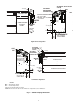
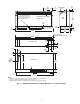
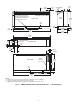
Step 1 — Check Jobsite —
Units are typically in-
stalled along an outside wall of the room. Refer to Fig. 1 and 2
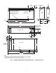
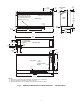
for an illustration showing piping locations. Install units with
adequate clearance to allow maintenance and servicing. Refer
to Table 1 and Fig. 3-14. Locate the console unit so that it pro-
vides adequate air circulation throughout the room.
Installation, operation and maintenance instructions are
provided with each unit. Before unit start-up, read all manuals
and become familiar with the unit and its operation. Thoroughly
check out the system before operation. Complete the inspections
and instructions listed below to prepare a unit for installation.
1. Compare the electrical data on the unit nameplate with
ordering and shipping information to verify that the cor-
rect unit has been shipped.
2. Keep both the chassis and cabinet covered with the ship-
ping carton until all plastering, painting, and finish work
is complete and it is time to install the chassis and cabinet.
3. Verify that the refrigerant tubing is free of kinks or dents,
and that it does not touch other unit components.
4. Inspect all electrical connections. Connections must be
clean and tight at the terminals.
Table 1 — 50PEC Physical Data
NOTES:
1. All units have grommet compressor mountings and TXV (ther-
mostatic expansion valve) devices.
2. All pipe sizes are in inches. Equivalent sizes in millimeters
follow:
WARNING
Electrical shock can cause personal injury or death. Before
installing or servicing system, always turn off main power
to system. There may be more than one disconnect switch.
Turn off accessory heater power if applicable.
IMPORTANT: The installation of console water source heat
pump units and all associated components, parts, and acces-
sories which make up the installation shall be in accordance
with the regulations of ALL authorities having jurisdiction
and MUST conform to all applicable codes. It is the respon-
sibility of the installing contractor to determine and comply
with ALL applicable codes and regulations.
CAUTION
To avoid equipment damage, do not use these units as a
source of heating or cooling during the construction pro-
cess. The mechanical components and filters used in these
units quickly become clogged with construction dirt and
debris which may cause system damage.
CAUTION
To avoid the release of refrigerant into the atmosphere, the
refrigerant circuit of this unit must only be serviced by
technicians who meet local, regional, and national profi-
ciency requirements.
BASE UNIT 50PEC 09 12 15 18
COMPRESSOR (Qty)
Rotary (1)
REFRIG. CHARGE (R-410A)/CKT (kg)
No. of Circuits
0.737
1
0.822
1
0.936
1
0.850
1
BLOWER
Motor kW
Wheel Size D x W (mm) 2 each
0.37
133 x 159
0.62
133 x 159
0.93
133 x 159
0.93
133 x 159
WATER CONNECTION SIZE
OD Sweat (in.)
Optional FPT Fittings (in.)
Optional MPT Fittings (in.)
1
/
2
1
/
2
1
/
2
1
/
2
1
/
2
1
/
2
1
/
2
1
/
2
1
/
2
3
/
4
3
/
4
3
/
4
CONDENSATE CONNECTION SIZE (ID Vinyl) (in.)
5
/
8
5
/
8
5
/
8
5
/
8
Air Coil Size (h x w) (mm)
203 x 660 254 x 660 254 x 660 254 x 812
FILTER SIZE (h x w x d) (mm)
Bottom Return
Front Return
254 x 762 x 25
178 x 749 x 3
254 x 762 x 25
178 x 749 x 3
254 x 762 x 25
178 x 749 x 3
254 x 914 x 25
178 x 800 x 3
CABINET SIZE (h x w x d) (mm)
Bottom Return With Standard 127 mm Subbase
Front Return With No Subbase
1219 x 660 x 305
1219 x 533 x 305
1219 x 660 x 305
1219 x 533 x 305
1219 x 660 x 305
1219 x 533 x 305
1372 x 660 x 305
1372 x 533 x 305
UNIT WEIGHT (kg)
Shipping
Operating
84
79
86
82
91
86
105
100
Unit Maximum Working Pressure (kPa)
Base Unit
Internal Secondary Pump
Internal Motorized Water Valve
Internal Autoflow Valve
3100
999
2067
3100
3100
999
2067
3100
3100
999
2067
3100
3100
999
2067
3100
in. mm
1
/
2
12.7
5
/
8
15.9
3
/
4
19.1