
Installation guide


literatureandattachedto the unit. Consult local building codes, the
current editions of the National Electrical Code (NEC) NFPA 70.
In Canada refer to the current editions of the Canadian electrical
Code CSA C22A.
Recognize safety information. This is the safety-alert symbol /_.
When you see this symbol on the unit and in instructions or
manuals, be alert to the potential for personal injury. Understand
these signal words; DANGER, WARNING, and CAUTION. These
words are used with the safety-alert symbol. DANGER identifies
the most serious hazards which will result in severe personal injury
or death. WARNING signifies hazards which could result in
personal injury or death. CAUTION is used to identify unsafe
practices which may result in minor personal injury or product and
property damage. NOTE is used to highlight suggestions which
will result in enhanced installation, reliability, or operation.
ELECTRICALSHOCK HAZARD
Failure to follow this warning could result in personal
injury or death.
Before installing or servicing system, always turn off main
power to system. There may be more than one disconnect
switch. Turn off accessory heater power switch if
applicable.
FIRE, EXPLOSION, ELECTRICAL SHOCK AND
CARBON MONOXIDE POISONING HAZARD
Failure to follow this warning could result in personal
injury, death or property damage.
A qualified installer or agency must use only
factory-authorized kits or accessories when modifying this
product.
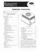
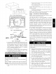
INTRODUCTION
The 50XZ heat pump is fully self-contained and designed for
outdoor installation. (See Fig. 1) Standard units are shipped in a
horizontal-discharge configuration for installation on a
groundlevel slab. Standard units can be converted to downflow
(vertical) discharge configurations for rooftop applications.
RECEIVING AND INSTALLATION
Step 1 -- Check Equipment
IDENTIFY UNIT
The unit model number and serial number are stamped on the unit
identification plate. Check this information against shipping
papers.
INSPECT SHIPMENT
Inspect for shipping damage while unit is still on shipping pallet. If
unit appears to be damaged or is torn loose from its anchorage,
have it examined by transportation inspectors before removal.
Forward claim papers directly to transportation company.
Manufacturer is not responsible for any damage incurred in transit.
Check all items against shipping list. Immediately notify the
nearest equipment distributor if any item is missing. To prevent
loss or damage, leave all parts in original packages until
installation.
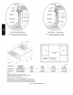
Step 2 -- Provide Unit Support
ROOF CURB
Install accessory roof curb in accordance with instructions shipped
with curb (See Fig. 5). Install insulation, cant strips, roofing, and
flashing. Ductwork must be attached to curb.
IMPORTANT: The gasketing of the unit to the roof curb is critical
for a watertight seal. Install gasketing material supplied with the
roof curb. Improperly applied gasketing also can result in air leaks
and poor unit performance.
Curb should be level to within 1/4 in. (3 m) (See Fig. 6). This is
necessary for unit drain to function properly. Refer to accessory
roof curb installation instructions for additional information as
required.
SLAB MOUNT
Place the unit on a solid, level concrete pad that is a minimum of 4
in. (102 mm) thick with 2 in. (51 mm) above grade (See Fig. 7).
The slab should extend approximately 2 in. (51 mm) beyond the
casing on all 4 sides of the unit. Do not secure the unit to the slab
except when required by local codes.
GROUND MOUNT
The unit may be installed either on a slab or placed directly on the
ground if local codes permit. Place the unit on level ground
prepared with gravel for condensate discharge.
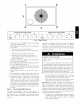
Step 3 -- Provide Clearances
The required minimum service clearances are shown in Fig. 2 and
3. Adequate ventilation and outdoor air must be provided. The
outdoor fan draws air through the outdoor coil and discharges it
through the top fan grille. Be sure that the fan discharge does not
recirculate to the outdoor coil. Do not locate the unit in either a
corner or under an overhead obstruction. The minimum clearance
under a partial overhang (such as a normal house overhang) is 48
in. (1219 mm) above the unit top. The maximum horizontal
extension of a partial overhang must not exceed 48 in. (1219 mm)
IMPORTANT: Do not restrict outdoor airflow. An air restriction
at either the outdoor-air inlet or the fan discharge may be
detrimental to compressor life.
Do not place the unit where water, ice, or snow from an overhang
or roof will damage or flood the unit. Do not install the unit on
carpeting or other combustible materials. Slab-mounted units
should be at least 4 in. (102 mm) above the highest expected water
and runoff levels. Do not use unit if it has been under water.
Step 4 -- Rig and Place Unit
Rigging and handling of this equipment can be hazardous for
many reasons due to the installation location (roofs, elevated
structures, etc.)
Only trained, qualified crane operators and ground support staff
should handle and install this equipment.
When working with this equipment, observe precautions in the
literature, on tags, stickers, and labels attached to the equipment,
and any other safety precautions that might apply.
Follow all applicable safety codes. Wear safety shoes and work
gloves.
INSPECTION
Prior to initial use, and at monthly intervals, all rigging brackets
and straps should be visually inspected for any damage, evidence
of wear, structural deformation, or cracks. Particular attention
should be paid to excessive wear at hoist hooking points and load
support areas. Brackets or straps showing any kind of wear in these
areas must not be used and should be discarded.
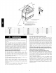
INSTALLATION
1. Remove unit from shipping carton. Leave top shipping skid
on the unit as a spreader bar to prevent the rigging straps
from damaging the unit. If the wood skid is not available,
use a spreader bar of sufficient length to protect unit from
damage.
2. Position the lifting bracket assembly around the base of the
unit. Be sure the strap does not twist.