
Installation guide


Unit
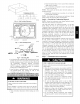
Rigging
Weight
Y
1 2
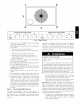
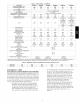
RIGGING WEIGHTS (SMALL CABINET)
024 030 036
Ib kg Ib kg Ib kg Unit
331 150 371 168 414 188 RiggingWeight
C00071
RIGGING WEIGHTS (LARGE CABINET)
042 048 060
Fig. 4 - Rigging Weights
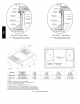
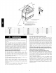
3. Place each of the 4 metal lifting brackets into the rigging
holds in the composite unit base.
4. Thread lifting bracket strapping around bottom perimeter of
unit as follows:
a. Open lever of tension buckle (ratchet type).
b. Feed strapping through tension buckle as shown in Fig.
8.
c. Pull strapping through tension buckle unit taut.
d. Snap lever down to lock strap in tension buckle. To
release strapping, squeeze safety latch, lift lever, and
pull webbing outward.
5. Tighten the tension buckle until it is taut. Lifting brackets
must be secure in the rigging holds.
6. Attach field-supplied clevis or hook of sufficient strength to
hole in the lifting bracket. (See Fig. 9)
7. Attach the 2 safety straps directly to the clevis or hook at the
4 rigging brackets. DO NOT attach the safety straps to the
lifting brackets (See Fig. 9).
8. Position lifting point directly over the unit's center of
gravity.
9. Lift unit. When unit is directly over the roof curb, remove
the 2 safety straps. Lower the equipment onto the roof curb.
10. After the unit is placed on the roof curb or mounting pad,
remove the top crating. On 50XZ060 units only, 2 wire ties
fastened to the outdoor coils and reversing
valve/accumulator assembly must be cut. Remove the left
and front louver panels and corner post to access wire ties.
The wire tie to be cut on the left is located approximately 4
in. (102 mm) down the tube sheet. The wire tie to be cut on
the right is located approximately 6 in. (152 mm) down the
tube sheet.
Step 5 -- Select and Install Ductwork
The design and installation of the duct system must be in
accordance with the standards of the NFPA for installation of
non-residence type air conditioning and ventilating systems,
NFPA 90A or residence-type, NFPA 90B and/or local codes and
ordinances.
Select and size ductwork, supply-air registers, and return air grilles
according to ASHRAE (American Society of Heating,
Refrigeration, and Air Conditioning Engineers) recommendations.
The unit has duct flanges on the supply- and return-air openings
on the side of the unit.
When designing and installing ductwork, consider the following:
PERSONAL INJURY HAZARD
Failure to follow this warning could result in personal
injury or death.
For vertical supply and return units, tools or parts could
drop into ductwork Install a 90 degree turn in the return
ductwork between the unit and the conditioned space. If a
90 degree elbow cannot be installed, then a grille of
sufficient strength and density should be installed to prevent
objects from falling into the conditioned space. Units with
electric heaters require 90 degree elbow in supply duct.
1. All units should have field-supplied filters or accessory
filter rack installed in the return-air side of the unit.
Recommended sizes for filters are shown in Table 1.
2. Avoid abrupt duct size increases and reductions. Abrupt
change in duct size adversely affects air performance.
IMPORTANT: Use flexible connectors between ductwork and
unit to prevent transmission of vibration. Use suitable gaskets to
ensure weather tight and airtight seal. When electric heat is
installed, use fireproof canvas (or similar heat resistant material)
connector between ductwork and unit discharge connection. If
flexible duct is used, insert a sheet metal sleeve inside duct. Heat
resistant duct connector (or sheet metal sleeve) must extend 24-in.
(610 mm) from electric heater element.
3. Size ductwork for cooling air quantity (cfm). The minimum
air quantity for proper electric heater operation is listed in
Table 2. Heater limit switches may trip at air quantities
below those recommended.