
Installation guide


B
A-B
1/4 (6.35)
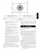
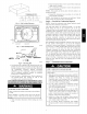
MAXIMUM ALLOWABLE
DIFFERENCE in. (mm)
B-C ArC
1/4 (6.35) 1/4 (6.35)
Fig. 6 - Unit Leveling Tolerances
A07925
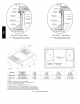
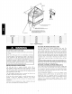
2"
(50.8ram)
±
ill_RETURN
AIR
IIIIIOPEN'NGt
IIIII /'
IIII| [[[
III1! I_l
IIIII....
IIIII \
IIIII
IIIII IIII
EVAR COIL COND. COIL
A07926
Fig. 7 - Slab Mounting Detail
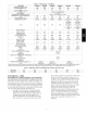
oo
FEED
C99067
Fig. 8 - Threading Belt
4. Seal, insulate, and weatherproof all external ductwork. Seal,
insulate and cover with avapor barrier all ductwork passing
through conditioned spaces. Follow latest Sheet Metal and
Air Conditioning Contractors National Association
(SMACNA) and Air Conditioning Contractors Association
(ACCA) minimum installation standards for residential
heating and air conditioning systems.
5. Secure all ducts to building structure. Flash, weatherproof,
and vibration-isolate duct openings in wall or roof
according to good construction practices.
CONVERTING HORIZONTAL DISCHARGE UNITS
TO DOWNFLOW (VERTICAL) DISCHARGE UNITS
ELECTRICAL SHOCK HAZARD
Failure to follow this warning could result in personal iniury
or death.
Before installing or servicing system, always turn off main
power to system. There may be more than one disconnect
switch.
1. Open all electrical disconnects before starting any servace
work.
2. Remove horizontal duct covers to access bottom return and
supply knock out panels.
3. Use a screwdriver and hammer to remove the panels in the
bottom of the unit base.
NOTE: These panels are held in place with tabs similar to an
electrical knockout.
4. Reinstall the horizontal duct covers (Fig. 11) to block off
the horizontal air openings.
NOTE: Avoid abrupt duct size increases and reductions. Abrupt
change in duct size adversely affects air performance.
Step 6 -- Provide for Condensate Disposal
NOTE: Ensure that condensate-water disposal methods comply
with local codes, restrictions, and practices.
The 50XZ units dispose of condensate through a 3/4 in. NPT
female fitting that exits on the compressor end of the unit.
Condensate water can be drained directly onto the roof in rooftop
installations (where permitted) or onto a gravel apron in ground
level installations. Install a field-supplied condensate trap at end of
condensate connection to ensure proper drainage. Make sure that
the outlet of the trap is at least 1 in. (25 mm) lower than the
drain-pan condensate connection to prevent the pan from
overflowing. Prime the trap with water. When using a gravel apron,
make sure it slopes away from the unit.
If the installation requires draining the condensate water away from
the unit, install a field-supplied 2 -in. trap at the condensate
connection to ensure proper drainage. Condensate trap is available
as an accessory or is field-supplied. Make sure that the outlet of the
trap is at least 1 in. (25 mm) lower than the unit drain-pan
condensate connection to prevent the pan from overflowing.
Connect a drain trough using a minimum of field-supplied 3/4-in.
PVC or field-supplied 3/4-in. copper pipe at outlet end of the
2-in. (51 mm) trap. (See Fig. 12) Do not undersize the tube. Pitch
the drain trough downward at a slope of at least 1 in. (25 mm)
every 10 ft (3 m) of horizontal run. Be sure to check the drain
trough for leaks. Prime the trap at the beginning of the cooling
season start-up.
Step 7 -- Install Electrical Connections
UNIT COMPONENT DAMAGE HAZARD
Failure to follow this caution could result in damage to the unit
being installed.
1. Make all electrical connections in accordance with NEC
ANSI/NFPA 70 (latest edition) and local electrical codes
governing such wiring. In Canada, all electrical
connections must be in accordance with CSA standard
C22.1 Canadian Electrical Code Part 1 and applicable
local codes. Refer to unit wiring diagram.
2. Use only copper conductor for connections between
field-supplied electrical disconnect switch and unit. DO
NOT USE ALUMINUM WIRE.
3. Be sure that high-voltage power to unit is within
operating voltage range indicated on unit rating plate. On
3-phase units, ensure phases are balanced within 2
percent. Consult local power company for correction of
improper voltage and/or phase imbalance.
4. Insulate low-voltage wires for highest voltage contained
within conduit when low-voltage control wires are in
same conduit as high-voltage wires.
5. Do not damage internal components when drilling
through any panel to mount electrical hardware, conduit,
etc.