
Installation guide


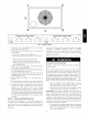
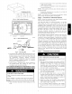


DETAIL A
SCALE 0.250
TIGHTEN STRAPPING SECURELY
WITH TENSION BUCKLE
INSTALL SAFETY STRAPS TO
RIGGING CLEVIS AT 4 RIGGING BRACKETS
SEE DETAIL A
PLACE RIGGING BRACKET ASSEMBLY IN 4
HAND HOLES AND INSTALL TIE DOWN STRAP
AROUND PERIMETER OF UNIT AND THROUGH
SPACE IN BRACKET ASSEMBLY
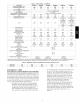
U NIT 50XZ A B
in, in, mm
024 19.0 18.25 463.6
030 19.0 18.25 463.6
036 20.0 19.0 482.6
042 20.0 2t .25 539.8
048 20.0 2t .25 539.8
060 2t .0 20.0 508.0
mm
482.6
482.6
508.0
508.0
508.0
533.4
Fig. 9 - Suggested Rigging
C99075
ELECTRICAL SHOCK HAZARD
Failure to follow this warning could result in personal injury
or death.
The unit cabinet must have an uninterrupted, unbroken
electrical ground. This ground may consist of an electrical
wire connected to the unit ground screw in the control
compartment, or conduit approved for electrical ground when
installed in accordance with NEC, ANSI/NFPA 70 American
National Standards Institute/National Fire Protection
Association (latest edition) (in Canada, Canadian Electrical
Code CSA C22.1) and local electrical codes.
HIGH-VOLTAGE CONNECTIONS
The unit must have a separate electrical service with a
field-supplied, waterproof disconnect switch mounted at, or within
sight from the unit. Refer to the unit rating plate, NEC and local
codes for maximum fuse/circuit breaker size and minimum circuit
amps (ampacity) for wire sizing.
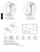
The field-supplied disconnect may be mounted on the unit over
the high-voltage inlet hole (See Fig. 2 and 3).
If the unit has an electric heater, a second disconnect may be
required. Consult the Installation, Start-Up, and Service
Instructions provided with the accessory for electrical service
connections.
Operation of unit on improper line voltage constitutes abuse and
may cause unit damage that could affect warranty.
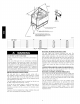
ROUTING POWER LEADS INTO UNIT
Use only copper wire between disconnect and unit. The
highvoltage leads should be in a conduit until they enter the duct
panel; conduit termination at the duct panel must be watertight.
Run the high-voltage leads through the power entry knockout on
the power entry side panel. (See Fig. 2 and 3 for location and size)
When the leads are inside the unit, run leads up the high-voltage
raceway to the line wiring splice box (See Fig. 13 through 17). For
singlephase units, connect leads to the black and yellow wires; for
3-phase units, connect the leads to the black, yellow, and blue
wires.
CONNECTING GROUND LEAD TO GROUND LUG
Refer to Fig. 15 and 16. Connect the ground lead to the chassis
using the ground lug in the wiring splice box.
ROUTING CONTROL POWER WIRES (24-V)
Form a drip-loop with the thermostat leads before routing them
into the unit. Route the thermostat leads through grommeted,
low-voltage hole provided in unit into unit control power splice
box. (See Fig. 2 and 3) Connect thermostat leads to unit control
power leads as shown in Fig. 15.
The unit transformer supplies 24-v power for complete system
including accessory electrical heater. An automatic-reset circuit
breaker (See Fig. 17) is provided in the 24-v circuit; see the
caution label on the transformer or Fig. 18. Transformer is factory
wired for 230-v operation. If supply voltage is 208-v, rewire
transformer primary as described in Special Procedures for 208-v
Operation section.