
Installation guide


UNIT SIZE
NOMINAL CAPACITY (ton)
SHIPPING WEIGHT (Ib)
(kg)
COMPRESSOR QUANTITY
TYPE
REFRIGERANT
REFRIGERANT METERING DEVICE
Refrigerant (R-410A) Quantity (Ib)
(kg)
METERING DEVICE ID
ORIFICE OD (in.) QTY
(mm)
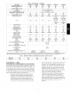
Table I - Physical Data - Unit 50XZ
50XZ024 50XZ030 50XZ036 50XZ042 50XZ048 50XZ080
2 2.5 3 3.5 4 5
388 408 451 508 531 551
167 185 205 230 241 250
1
SCROLL COMPRESSOR
R- 410A
Indoor-TXV Outdoor-Accurater
7.5
3.4
TXV
0.035 (2)
(.89)
8.2
3.7
TXV
0.035 (2)
(.89)
9.7
4.4
TXV
0.038 (2)
(.97)
11.0
5.0
TXV
0.038 (2)
(.97)
11.5
5.2
TXV
0.038 (Left OD
Coil)
0.046 (Right
OD Coil)
(.97 Left OD
Coil)
(1.17 Right OD
Coil)
13.5
6.1
TXV
0.042 (Left OD
Coil)
0.052 (Right
OD Coil)
(1.07 Left OD
Coil)
(1.32 Right OD
Coil)
OUTDOOR COIL l
Rows... Fins/in. 2...21 2...21 2...21 2...21 2...21 2...21
face area (sq. ft.) 12.3 12.0 13.6 15.4 17.4 19.3
OUTDOOR FAN
Nominal Airflow (CFM) 2700 2700 2800 2800 3300 3300
Diameter (in.) 22 22 22 22 22 22
(mm) 559 559 559 559 559 559
Motor HP (RPM) 1/8 (825) 1/8 (825) 1/8 (825) 1/8 (825) 1/4 (1100) 1/4 (1100)
INDOOR COIL
Rows... Fins/in. 3...15 3...15 4...15 3...15 4...15 4...15
face area (sq. ft.) 3.7 3.7 3.7 4.7 4.7 5.7
INDOOR BLOWER
Nominal Airflow (CFM) 800 1000 11 O0 1400 1450 1750
Size (in.) 10x10 10x10 1lx10 1 lx10 1lx10 1lx10
(mm) 254x254 254x254 279x254 279x254 279x254 279x254
Motor (H P) 1/2 1/2 3/4 3/4 3/4 1.0
HIGH- PRESSURE SWITCH (psig) 650_+15
Cutout
Reset (Auto) 420_+25
LOSS- OF- CHARGE/LOW- PRESSURE
SWITCH 20_+5
(Liquid Line) (psig) 45_+10
Cutout
Reset (Auto)
RETURN-AIR FILTERS throwaway* (in.) 20x20x1 20x24x1 24x30x1
(mm) 508x508x25 508x610x25 610x762x25
*Required filter sizes shown are based on the larger of the ARI (Air conditioning and Refrigeration Institute) rated cooling airflow or the heating airflow velocity of
300 ft/minute for throwaway type or 450 ft/minute for high-capacity type. Air filter pressure drop for non-standard filters must not exceed 0.08 in. wc.
Table 2 - Minimum Airflow for Reliable Electric Heater Operation (Cfm)
UNIT-5OXZ 024 030 036 042 048 060
AIRFLOW 750 1025 1250 1400 1710 1800
EASY SELECT TM - 50XZ
EASY SELECT CONFIGURATION TAPS FOR 50XZ
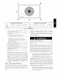
Easy Select taps are used by the installer to configure a system. The
ECM motor uses the selected taps to modify its operation to a
pre-programmed table of airflows. The unit must be configured to
operate properly with system components with which it is installed.
To successfully configure a basic system (see information printed
on circuit board label located next to select pins), move the 6 select
wires to the pins which match the components used.
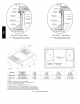
a. AUX HEAT kW/CFM-SELECT HEATER RANGE
FOR SIZE OF ELECTRIC HEATER INSTALLED
Installer must select the auxiliary heat airflow approved
for application with kW size heater installed. If no
heater is installed, this step can be skipped. Each select
pin is marked with a range of heaters for which airflow
(also marked), is approved. For increased comfort, select
the narrowest kW range matching the heater size, for
example, 0-10 for 10-kW heater. This airflow must be
greater than the minimum for CFM for electric heater
application with the size system installed for safe and
continuous operation. (See Tables 3, 4, 5, 6 & 7 for
airflow delivery and n_ininmm CFM.) Note that airflow
marked is the airflow which will be supplied in
emergency heat mode and heating mode on air
conditioners when electric heat is the primary heating
source. In heat pump heating mode when electric
heaters are energized, the ECM will run the higher of
heat pump heating airflow and electric heater airflow to
ensure safe heater operation. The factory selection is the
largest heater range approved (See Fig. 19, A as
indicated).